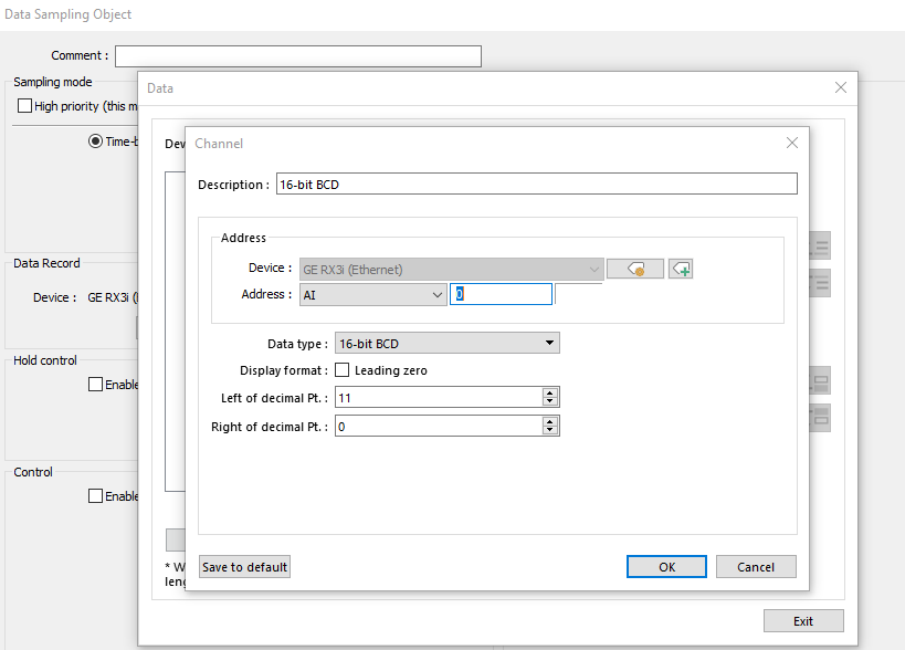
Is it possible to data sample a discrete tag? I want to use trigger based sampling for several discrete tags in the PLC. The only option for the channel are registers, not bits. This is for a GE RX3i controller, the only tag types available are AI, AQ and R.
All the points I want to log are discretes in the PLC. They don’t need to be alarms and the operation log settings only seem to work when a button is pressed on the Weintek HMI, not when a PLC bit changes.
Currently, the data sampling object does not support boolean tags. In most applications we recommend using the “Event (Alarm) Log” to perform this function. However, I may be able to advise an alternative method. Can you state approximately how many boolean tags you would like to monitor within the data sampling object? Also, please advise as to how often you wish to record their current state.
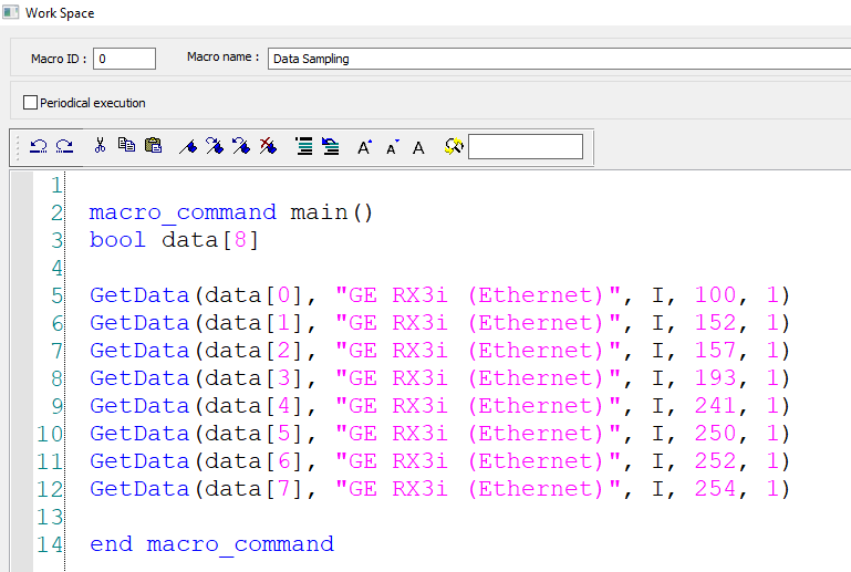
I only need to monitor 8 boolean tags. I have them set up contiguously in the PLC. The reason for this is to assist with troubleshooting an issue at a remote site. I need to have 1 second or less resolution.
I have it set up to monitor a 16 bit register with 0.1 second time samples. It would be nice to have this trigger based
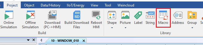
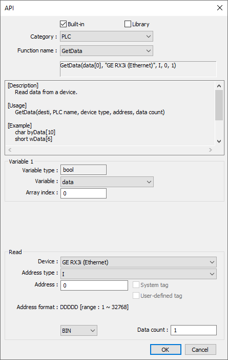
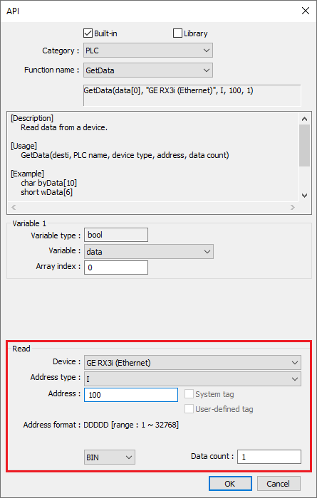
To work around this limitation I would recommend that you transfer your boolean data into local registers and then monitor these registers within the “Data Sampling Object”. This can be accomplished via the following method:
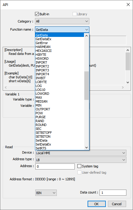
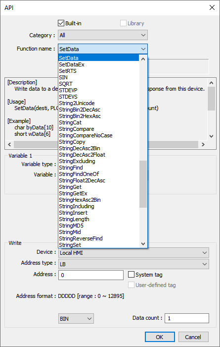
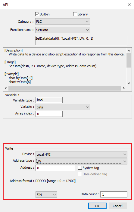
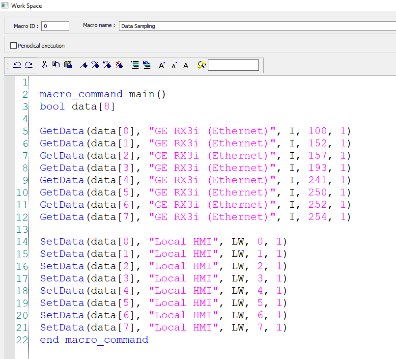
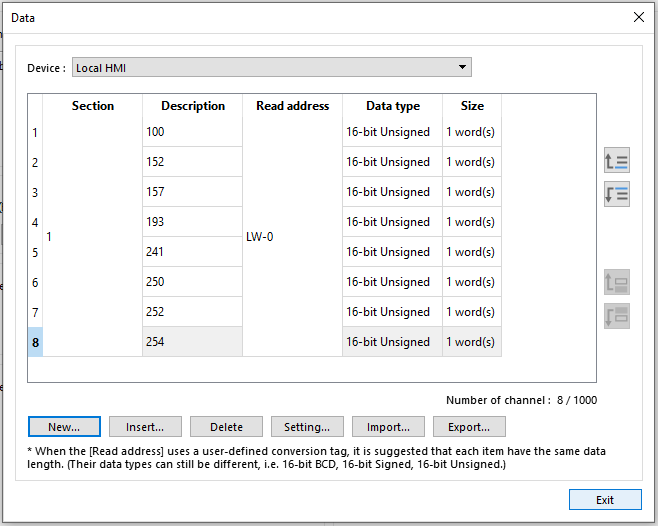
Click “Ok” when finished and then repeat steps 9-12 for each boolean register and write them into a set of contiguous registers within the HMI’s LW memory: Example: This data is written into register LW-0 - LW-7.
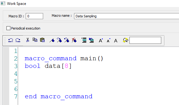
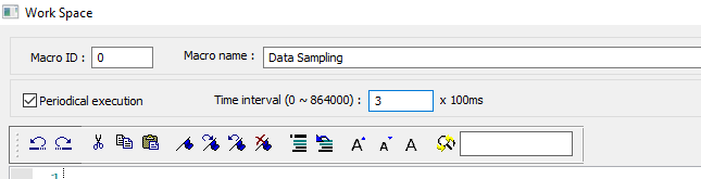
Ensure that “Periodical execution” is enabled and define the execution time as 2 x 100ms:
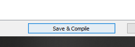
Click “Save & Compile” when finished:
Within your data sampling object, read LW-0 - LW-7 as within this example or the appropriate range of LW registers that you defined within steps 9- 12 to record the current value of the boolean registers: