Introduction:
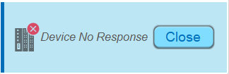
In some cases, the “Device No Response” message may appear during the initial configuration of communication between devices. While it may seem difficult to diagnose, there are several steps you can follow to determine the cause of the communication issue. This post outlines troubleshooting methods used to determine and resolve most common issues.
What causes the “Device No Response” message?
In most cases, a “Device No Response” error can be traced to one of the following causes:
- Incorrect communication parameters
- Invalid tag or registers used in the project
- Incorrectly designed or broken cable
To make the troubleshooting process easier, it’s important to find the connection guide for your specific PLC.
Instructions for Downloading Your Specific Connection Guide:
To find a connection guide for the PLC driver used within your project, navigate to the Supported Devices shown below:
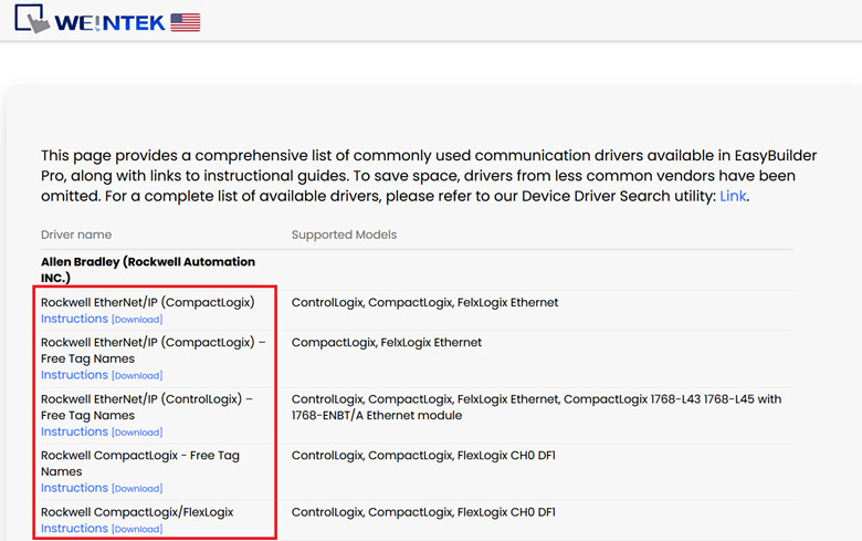
Here you will find a list of the most common drivers used by customers in North America, the connection guides, and the PLC models that each driver was validated with.
FAQ:
Q: Where does the “Device No Response” error come from?
The UI of the “Device No Response” popup is defined on Window 5 within every EasyBuilder Pro project. Window 5 is a reserved system window included in every EasyBuilder Pro project by default. It is responsible for displaying this error message whenever a communication issue is detected.
Q: Can I just delete window 5 to get rid of the message?
While it is possible to delete window 5, it is not recommended as doing so will only mask the error message without resolving the underlying issue. This could lead to other anomalies down the line that become much harder to diagnose, since the HMI would no longer have a way to visibly alert the user. It is always better to resolve the root cause of the error, instead of hiding it.
Q: What are CODESYS enabled HMIs and how do they affect Ethernet communication?
In some cases, users may have a Weintek HMI with an active CODESYS runtime license. This license allows the unit to run our built-in CODESYS soft PLC which operates alongside the HMI runtime. It is important to note that when activated, CODESYS will control the LAN 1 port on the unit and the CAN bus port if applicable. This means that the HMI runtime cannot communicate out of LAN 1 or the CAN bus port. As such, if there is a device connected to either of the ports controlled by CODESYS on a CODESYS activated unit, and the HMI runtime is attempting to reach that device, a “Device no response” message will display since it is only CODESYS that can communicate using these ports.
Q: Can the port number configured in my project cause a communication error?
In most cases, the port number is pre-configured by the developer for the respective protocol and does not need to be adjusted. As an example, Modbus TCP uses port 502 by default and this is loaded automatically. However it is possible that the port number may have been changed by the programmer, so be sure to verify that the port number set in EasyBuilder Pro and the PLC are matching.
Using the Diagnoser tool:
The Diagnoser is a built-in diagnostic tool that allows users to monitor communication activity in real time from your simulation or HMI. When dealing with a “Device No Response” error, the Diagnoser can help to pin point the exact object or packet request that is failing, which makes it an invaluable step in the troubleshooting process.
Note: The Diagnoser tool discussed is only usable with HMI models belonging to the cMT & cMT-X series, older legacy models do not have access to the tool described below.
Enabling the Diagnoser:
-
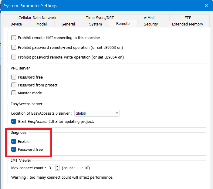
From within your EasyBuilder Pro project navigate to the system parameters in the upper taskbar
-
In the system parameters settings, select the remote tab.
-
Scroll down to find the Diagnoser section, check enable and optionally set a password.
-
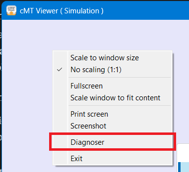
Once enabled, run an online simulation and while the cMT viewer window is open, right-click anywhere on the window to open the drop-down menu.
-
Select Diagnoser from the dropdown menu.
Navigating the Diagnoser:
The Diagnoser tool comes with several tabs along the top:
- Object
- Device
- Packet
- Macro
- MQTT
- OPCUA
When troubleshooting a “Device No Response” error, the two most relevant tabs are the Object and Packet tab.
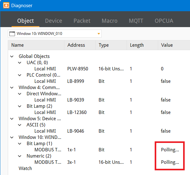
Object Tab:
The Object tab displays all of the objects in your project organized by window, showing each object’s name, address, data type, length, and current value.
When an object is successfully communicating with the PLC, the status in the value column will reflect the data being read. However, if an object shows the status “Polling…” this indicates that the HMI has not received a response to the packet request.
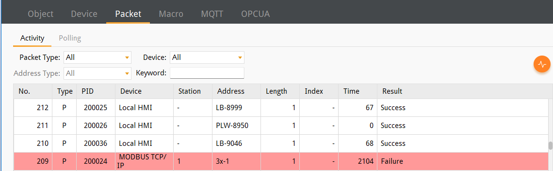
Packet Tab:
The Packet tab functions similarly to other network analysis tools, capturing all packet or frame communication in real time. Each packet is logged with details including it’s type, device, station, address, and result.
When a communication failure occurs, the affected packet will be highlighted in red with a result of “Failure”, a straightforward way to identify which device or device value request is not receiving a response.
Discovering what is causing the issue:
The “Device No Response” error is a generic communication error message indicating that the HMI did not receive a response to at least one value request. It does not necessarily mean that communication has failed as a whole. So, it is important to determine what is causing the issue and narrow the scope. These are some areas where issues may be present:
- Global Object Issue(s)
- Local Object Issue(s)
- Ethernet Communication Issue(s)
- Serial Communication Issue(s)
Global Object Issue:
Indication: The “Device No Response” error happens consistently across all pages in the project, and the HMI can still read ‘some’ PLC data just fine.
Global objects run as background tasks and will run continuously throughout the project, regardless of which window or page is currently active. Some examples of global objects include:
- Data sampling
- Alarms
- Scheduling
- Macros
- Data Transfer (Global)
- PLC Control
- Condition
- Action Trigger (global)
- Timer (global)
- Backup (Global)
- Scheduler
- MQTT
Because these objects operate in the background, a communication error that is tied to one of these objects will show up throughout the entire project.
Local Object Issue:
Indication: Only specific pages or individual objects are affected, while the rest of the project functions normally.
Unlike global objects, local objects are tied to a specific page on which they are placed and operate only when that page is active. Some examples of local objects are numeric displays or bit lamps. If an error is present, you may notice that certain objects are missing from the affected page.
This is intentional, as the HMI cannot verify the actual state of the device value, displaying a default value would give the operator a false impression of the status. Hidden objects help to prevent the operator from mistaking the machine’s state.
Some objects will display regardless, the distinction here is that if an object exists solely to “write” a value, it will have no issue displaying on the HMI. However, if it contains a “read” address and attempts to poll the value of a tag or register that cannot be read it will not display.
Ethernet Communication Issues:
Indication: The HMI does not communicate with the PLC at all. When this happens, most PLC related objects will not display, and global objects dependent on PLC values will not work.
While using an Ethernet-based connection, multiple configuration points will have to be correctly implemented for communication to succeed.
-
HMI IP Address: Verify that the IP address on the HMI has been configured correctly and follows the desired network scheme
-
PLC IP Address: Verify that the IP address is configured correctly on the PLC that is involved in the communication
-
PLC IP Address in HMI project: Finally, verify that the IP address in your EasyBuilder Pro project is configured in a matching scheme to that of your HMI and PLC

Port Number: Most of the time, the port number is pre-configured by the driver and will not need to be adjusted. For example, Modbus TCP uses port 502 by default. Though it is possible this might have been changed within the PLC software.
LAN Port Subnet Separation: Most Weintek HMIs have two LAN ports, LAN 1 and LAN 2. It is critical that these two ports are configured on separate subnets. If they share the same subnet, a communication error will occur. In addition, you should also ensure that one of the subnets matches that of the PLC that the HMI is communicating with.
Note: The HMI runtime on a Weintek HMI with an active CODESYS license will not have access to certain ports. See CODESYS Enabled HMIs.
Serial Communication Issues:
Serial communication has its own set of configuration requirements, similar to Ethernet. The baud rate, parity, data bits, and stop bits should match between the HMI and the PLC.
Indication: Similar to Ethernet issues, a serial communication failure will also result in complete communication failure, most PLC related objects will not display, and global objects dependent on PLC values will not work.
Communication Parameters: Ensure that the Baud Rate, Data Bits, Stop Bits, and Parity settings are identical on both the HMI and the PLC. If even one of these fields is incorrect on either end it will either prevent communication entirely or cause communication / data anomalies.
Unit ID/Slave Number: These are values that function similarly to IP addresses in an Ethernet network, identifying the specific device using a serial connection on the network. Default values will vary by vendors, some devices use 1, others may use 255 as the default or more likely, you have already configured this on the device itself. Because of this, it is important to verify this value in your device’s documentation or as set within the software or via the hardware of the device.
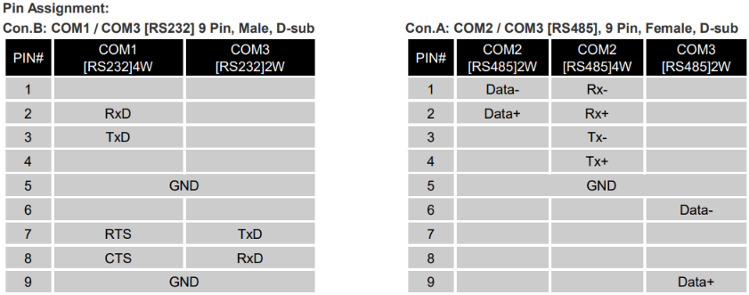
Cable Pinout: This is by far the most common cause of serial communication errors. In many cases, serial cables are custom-built, and an incorrect pinout will prevent communication even if all other software settings are configured correctly. If configuration has been verified and communication still isn’t working, the serial cable connection should be the first hardware component inspected. Every manufacturer lists the pinout of the serial ports on their products. This information is typically listed on their website or in the device documentation
If while using a pre-designed cable a communication error occurs, we often recommend replacing the cable first, before doing deeper troubleshooting of your configuration. If you plan to build your own cable, it can be quite helpful to prototype the cable with a solderless DB9 adapter. This can iron out unexpected results from your serial connection, before a more permanent configuration has been set.
Troubleshooting Steps:
Troubleshooting Global Object Issues:
If the “Device No Response” error is present across all pages of your project, a global object misconfiguration is the likely culprit. The steps below walk through how to identify and fix the issue.
-
Confirm the communication error exists on every page by navigating through the windows of your project while running an online simulation or downloading to the HMI. If you have trouble identifying which tag or register is causing the issue, then refer to the Diagnoser section for a step-by-step guide on using the Object and Packet tabs.
-
Open your EasyBuilder Pro project, and review the global objects, data sampling, alarms, scheduling, macros, data transfers, condition objects, timer objects, and MQTT. Confirm that the tags and registers referenced by each are still valid.
Note: If you want to rapidly test objects, simply delete certain objects and test the project. For example, you can delete all alarms then download the project to the HMI. If the issue was resolved then it was likely due to the alarms. Repeat this process with other object types until the project is functional once again.
-
A tag name or type mismatch is a common issue. If someone has edited the PLC project by renaming or readdressing a variable, (even if just one character is different) then this change must be reflected in the HMI project to allow communication. Cross reference tag names configured in your global objects, against tag names in the PLC project.
-
Additionally, you can and should generate a new tag file using your latest PLC app build and import the tag file as a first step. Our software compiler will likely catch any errors such as a tag name mismatch before the project is downloaded.
-
In addition, if you are working with a register-based PLC, verify that the register range is correctly referenced and do so from within the PLC project. Some PLC models allow the memory range to be configured, and if a register is not within range, then the PLC may return an error. While this is not common, some users still encounter this issue. To determine the appropriate addressing convention, select the settings button next to the address field in EasyBuilder pro.
-
If an error is found, navigate to the affected global object in EasyBuilder Pro and update the tag name or register address to match the PLC configuration. Once updated, run an online simulation or download the project once again and verify the issue is resolved.
Troubleshooting Local Object Issues:
If the “Device No Response” error only appears on specific pages, or if certain objects are hidden while the rest of the project remains unaffected, it is likely that the issue is related to an object on that page.
-
To begin, run an online simulation while the PC is connected to the PLC or download the project to your HMI. Once the project is running, take note of any objects that do not appear. These are the primary visual indicators that a local object communication error is present.
-
Navigate through each window of your project systematically, while taking notes of which pages show the “Device no response” message and contain objects that do not display. This will make it easier to identify the problem.
-
Once the affected object has been identified, open the window in EasyBuilder Pro and review object settings. Double click on any suspicious object to open the configuration settings and verify that any tag names or register addresses that reference the PLC use the correct naming convention and use a valid address. Pay close attention to the data type, length, and security settings to ensure that not only is the correct address referenced but also that no other object settings may result in the communication issue.
-
If a mismatch is found, correct the tag name, register address, or data type within the object’s settings and run the simulation again to verify the issue has been resolved.
Troubleshooting Ethernet Issues:
If there is no communication with the PLC and some or all UI objects addressed to the PLC fail to display, the issue is likely rooted in the Ethernet configuration. The steps below walk through the most common Ethernet issues and how to resolve them.
Note: If you are using a CODESYS enabled HMI, there are additional network considerations to be aware of, refer to the Background & Overview section for more details.
-
Confirm the communication issue is present across the entire project by navigating through multiple windows within an online simulation or on the HMI itself after downloading to the HMI. If no objects on any page display up-to-date PLC data proceed with the next steps.
-
Verify LAN port subnet separation - Most Weintek cMT-X HMIs have two LAN ports, LAN 1 and LAN 2. It is important that these ports are configured to different IP subnets. If both ports share the same subnet, a communication error will occur. To check, navigate to the HMI’s network settings and confirm that LAN 1 and LAN 2 are on separate IP subnets.
-
Verify IP configuration - There are three places where IP addresses need to be configured for Ethernet communication to succeed.
- HMI IP Address: Navigate to the HMI network settings and confirm that each IP address assigned to the LAN port used for PLC communication is valid and does not conflict with other devices on the network.
- PLC IP Address: Confirm that the PLC itself has a valid IP address configured on the same subnet as the HMI.
- Project IP Address: Inside of your EasyBuilder Pro project, navigate to System Parameters and open the Device tab, confirm that the IP address configured for your PLC device matches the actual IP address of the PLC.
- Port Number: While reviewing the device settings, also confirm that the port number has not been altered from the default value. If the port number has been changed within the PLC software ensure that the value in your EasyBuilder Pro project matches
-
If all IP configurations appear correct and communication is still not established, our suggestion is to remove any communication middlemen, such as routers or switches. Afterwards, connect your HMI back to the network and attempt communication.
Troubleshooting Serial Issues:
Serial communication failures will also cause some or all UI objects addressed to the PLC to fail to display. In addition, global objects that reference PLC addresses will not function as intended.
-
Confirm that the communication issue is present across the entire project by navigating through multiple windows during an online simulation or after downloading to the HMI. If no objects on any page are displaying data proceed with the next steps.
-
Verify Communication Parameters - Navigate to the System Parameters in EasyBuilder Pro and open the Device tab. Confirm that the following four parameters have the correct configuration and match that of the PLC:
- Baud Rate
- Data Bits
- Stop Bits
- Parity
-
Verify Unit ID / Slave Number - The Unit ID or Slave Number identifies the specific device on the serial network, functioning similarly to an IP address. The value must match what is configured on the PLC itself. Additionally, verify that the project references a slave device that actually exists. Default values tend to vary by vendor, so it’s always safe to check before assuming. Verify this value against your device’s documentation or the configuration within your PLC software.
-
Verify Cable Pinout - If all configuration has been verified, use the Diagnoser to confirm packets are being sent with no response, at this point the serial cable is the most likely culprit. Cable pinout issues are the most common cause of serial communication failures. First cross reference the pinout of your cable from the official data sheet of your HMI and PLC, most manufacturers will list this pinout documentation on their website. Here is an example of one such diagram.
-
Depending on your situation, use one of the following methods to troubleshoot your cable.
- If you are using a pre-made cable, and communication cannot be established despite correct configuration, replace the cable first before performing deeper hardware inspection.
- If you are using a custom cable, prototyping with a solderless DB9 adapter is an efficient way to test the pinout without having to rebuild the cable altogether.