I don’t know if something has become damaged or perhaps I’m not reading the wiring diagram correctly on my iR-DM-16-N.
I am using wires to go from each output to a relay card. I would like the outputs to energize the coil. For some reason when I connect a 24V wire to UG as shown on the diagram, each output wire has voltage even though they aren’t ON, and also when I try to use the HMI to turn them on and off (even with any power disconnected from the card) I may get an output to flicker for a split second and then turn off.
Do you think this is an indication that the I/O card is now faulty? Shouldn’t I be able to have the outputs light up on the card even when they aren’t wired to anything? I see that the outputs are sinking, so perhaps I’m not wiring it up correctly but I’ve become very confused by the wiring diagram and how it’s behaving. Any help would be appreciated!
Within your application are you using our Ethernet coupler the iR-ETN? If so, can you use EasyRemote IO to turn on and off the output logic and test the voltage while doing so? Also, can you advise the voltage that you measure on an output that is not “on”?
Note: Here is a link to the EasyRemote IO user manual.
So we figured out one issue, which leads to another question. But two things:
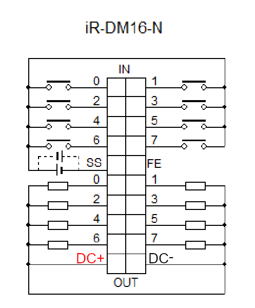
-How exactly is the bottom of the card supposed to be wired? Does the 24V go in the bottom left, while the common goes into the bottom right? At the moment, we don’t have any voltage (when on or off), but the outputs are firing again (in remote I/O and on LEDs on card).
-The outputs weren’t firing because further down the ladder, I was de-energizing the coil too each scan. Which leads me to another question (How do I set up multiple instances to energize a coil if they will conflict with each other even when the conditions to the left aren’t met?