HMI: cMT3162X + Codesys activation
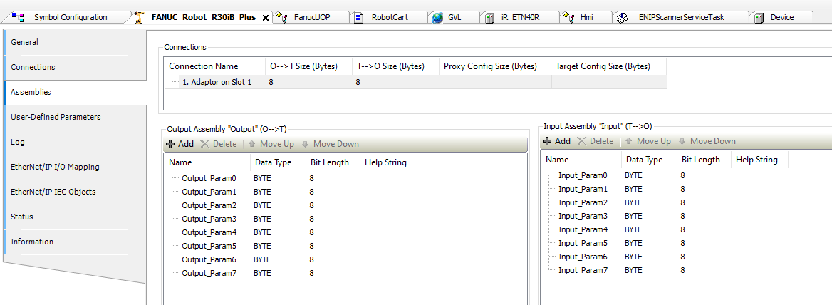
I have a customer wanting to use a Codesys enabled Weintek HMI for a robotic application. Communication with the Fanuc robot will be over Ethernet IP and they’ve supplied me with an EDS file. Importing it went fine and it now shows 8 bytes of input, 8 bytes of output.
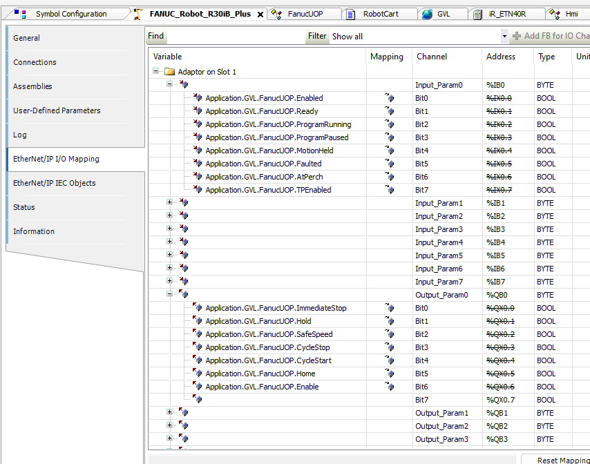
Some of which have already been assigned to UOP signals.
What is the method for adding INT values for things like reading a fault code, sending a speed command, etc? In the past I’ve only done this with other platforms so I want to be sure that I know how to add it correctly in Codesys so that it corresponds with the right location in the Fanuc as well.
Hi @JDControlsLLC,
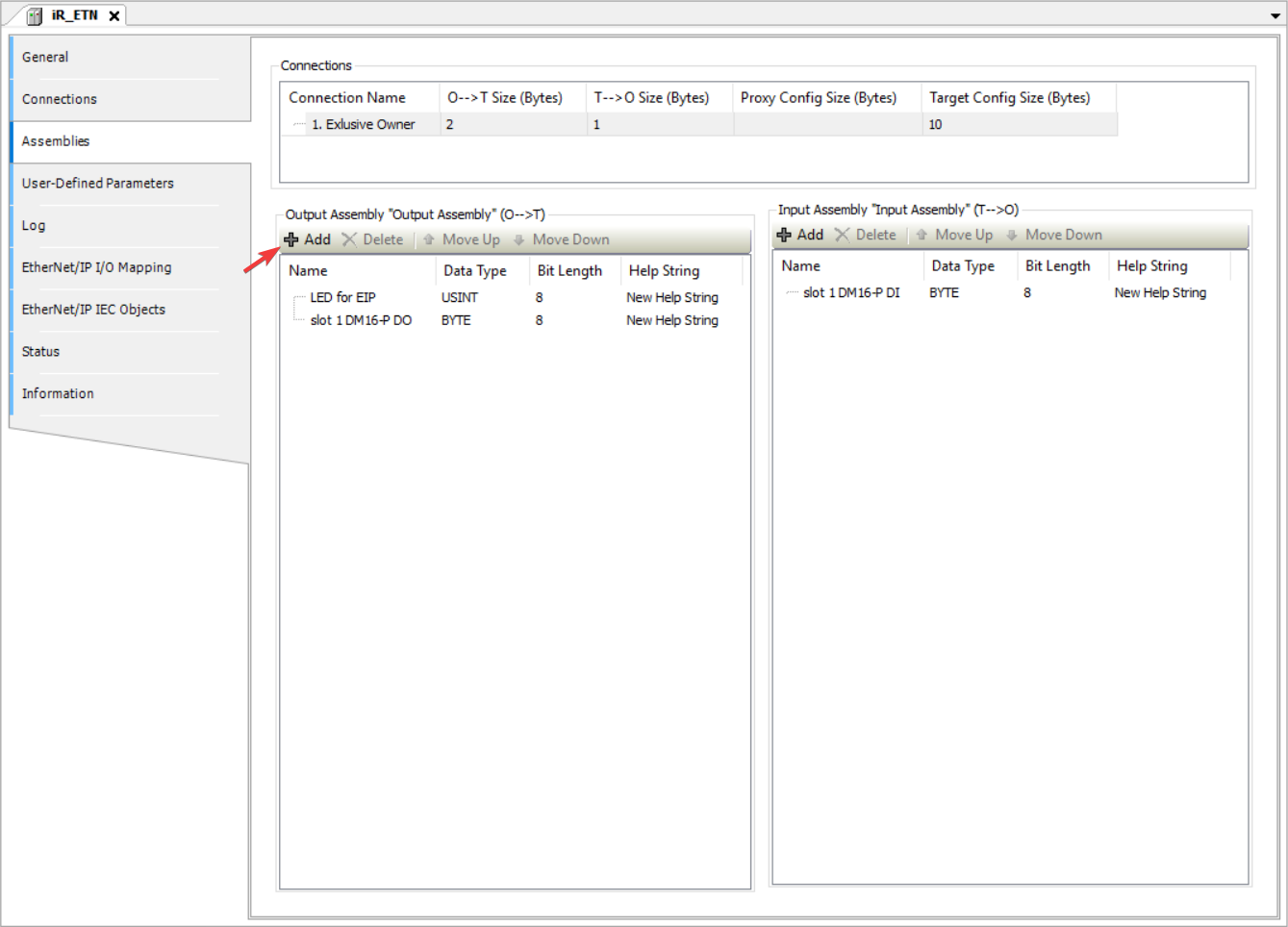
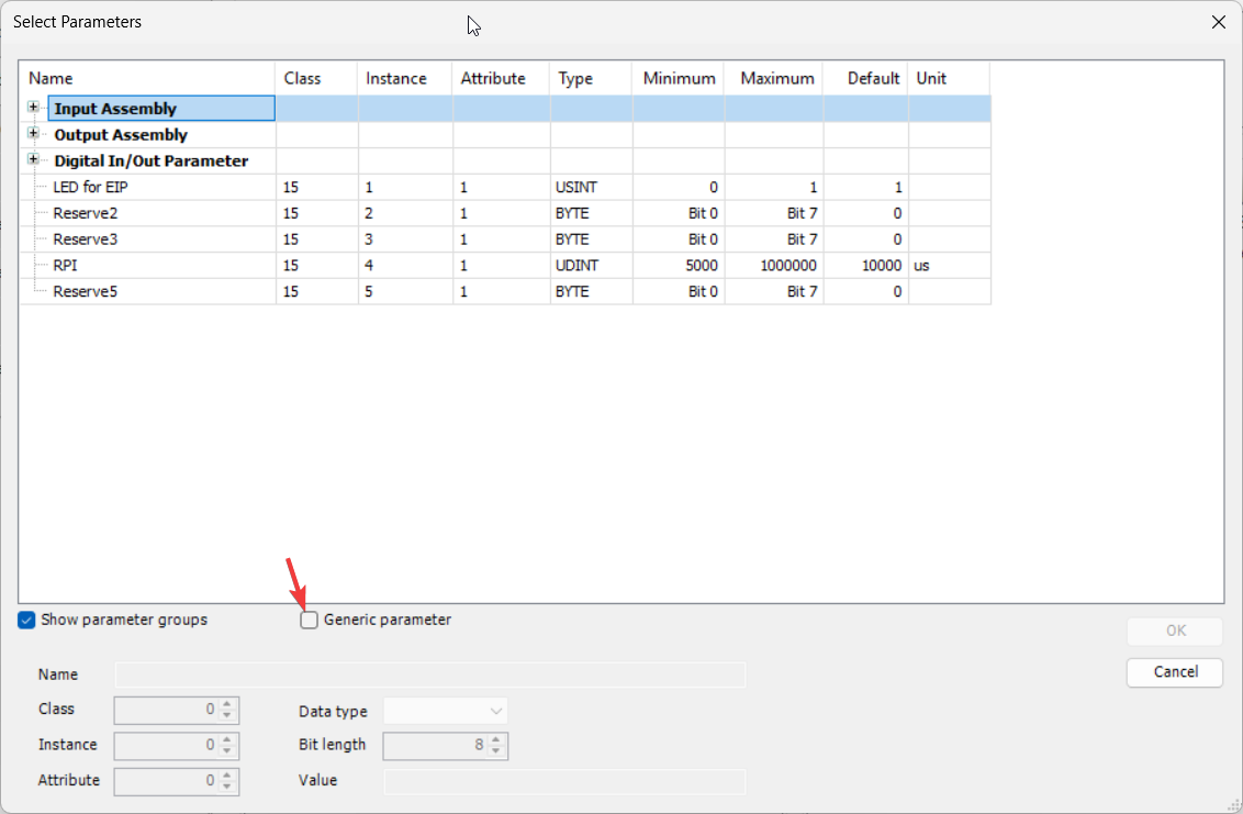
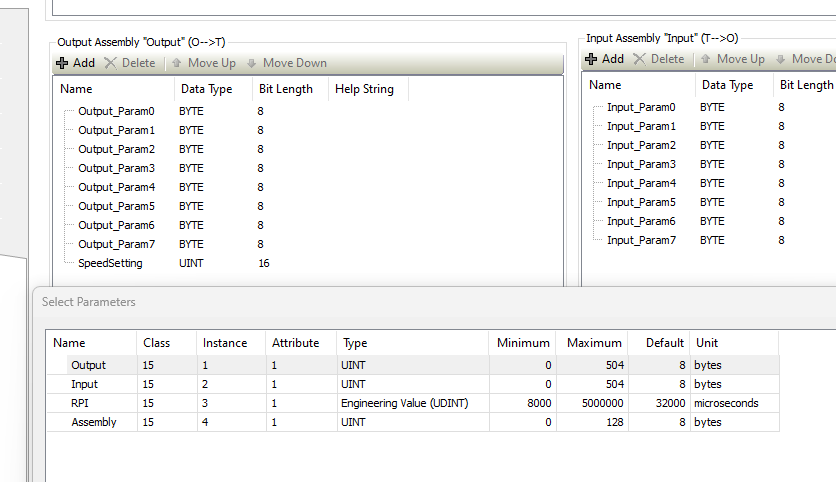
To add a new mapping point within the EtherNet/IP I/O mapping tab, use the “Add” button within the “Assemblies” tab to add a new pre-defined or “generic” (user-defined) parameter:
Note: When adding a “generic” parameter for a point not already found within the EDS file, you will need to know the CIP path values (class, instance, and attribute).
Ok I added an output for a speed percentage command.
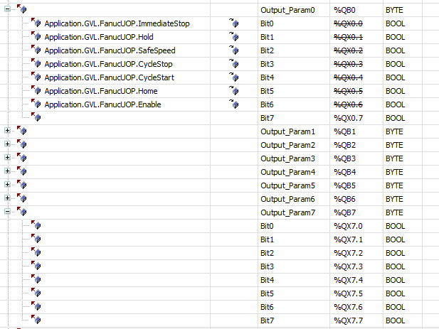
Is it correct to just assume that these are going in order starting at DI[0] and DO[0] in the Fanuc?
Meaning that if the Fanuc is configured for 8 bytes of input and 8 bytes of output, like the EDS file contained that my customer supplied to me, that %QX0.0 - %QX7.7 from Codesys writes to DI[0]-DI[63] on the Fanuc?
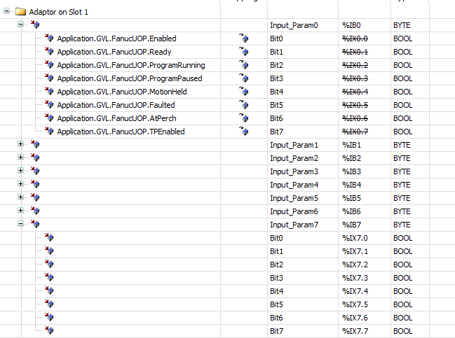
From the Fanuc, DO[0]-DO[63] should write to %IX0.0 - %IX7.7?
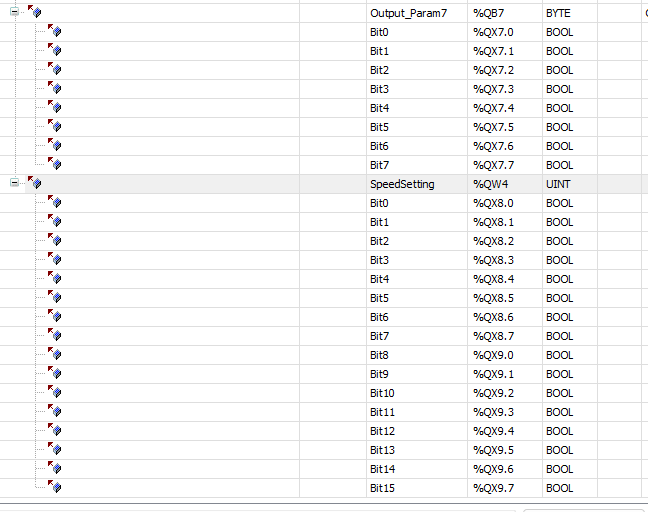
And it would follow that now this UNIT output for speed command that I just added would write to DI[64]-DI[79] as long as the Fanuc programmer has added that block of DI on his end? It is added right after the 8 bytes of outputs. That’s also shown in the first screenshot of this reply.
@JDControlsLLC,
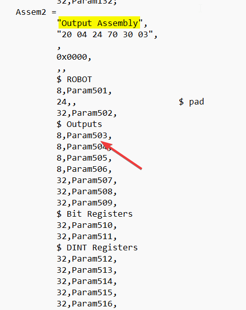
The parameters should follow what is set within the EDS file and should be listed in order. If you open the EDS file you should see the “Param” name next to each byte within the output assembly located near the bottom of the file:
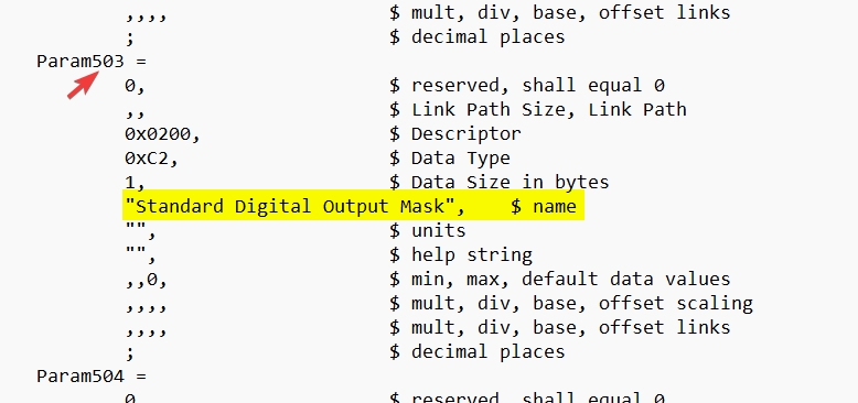
In my experience, usually the output IO is listed in sequential order in this section. However, with some points you can cross-reference the param name to help verify what it is actually targeting:
The “Output_Param1” ~ “Output_Param7” are likely names added by the vendor within the EDS. The EDS may have meaningful descriptions that can help you verify what you are reading and writing.
Brendon,
Just replying to post my results in case this helps someone else out.
Got back today from this startup and everything went well. I was a bit, literally, off on my DI/DO numbering on a previous post about the Fanuc as it starts at 1, not 0.
As long as the Fanuc side is configured to start at DI[1] and DO[1] then the 8 bytes of inputs to Codesys correspond to DO[1]-DO[64] and the 8 bytes of outputs correspond to DI[1]-DI[64] in Codesys.
Adding the INT worked just as you explained. On the Fanuc side, we configured Group Input GI1 to start at 65 and use 16 bits. So that means the INT value I’m sending from Codesys would be sent to DI[65]-DI[80]. Same structure for the INT value sent from Fanuc to Codesys. Group Output GO0 was used for that.
One thing to note is that Fanuc uses 16 bit words whereas Codesys was set up for bytes per the EDS import.
So the Ethernet/IP connection on Fanuc had to be set up for a size of 5 for input, 5 for output. That totals 80 bits, the exact same size I had configured in Codesys once I added the INT value on the input and output.
If the size doesn’t match, the connection will fault.
1 Like
@JDControlsLLC,
Thank you for sharing your solution! We work with plenty of engineers that use the - Fanuc R30iB - so this is bound to help someone out.