Introduction:
Within this post, we demonstrate how to log and view alarm history on iP, iE, XE, eMT, and mTV series HMIs.
Software Version:
EasyBuilder Pro 6.03.02.463+
Instructions:
-
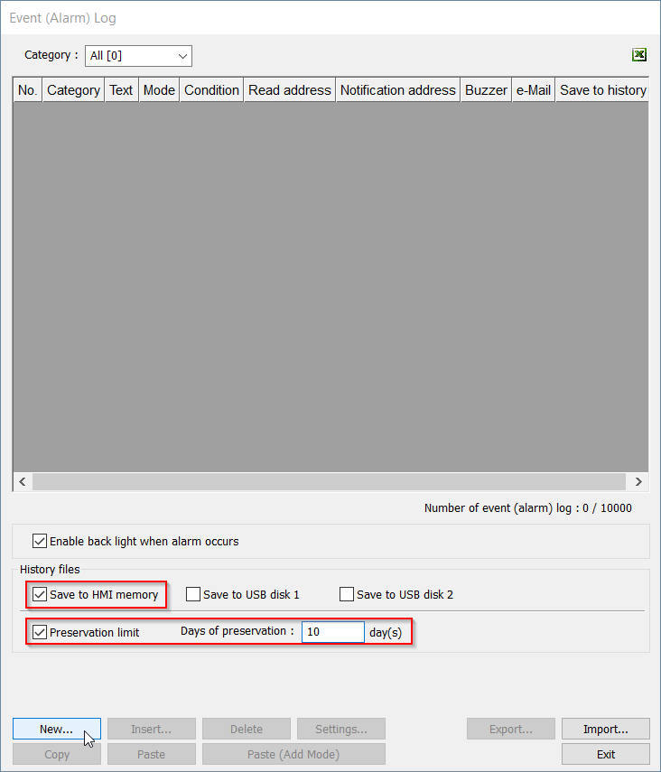
Begin by navigating to the “Data/History” tab and selecting the “Event (Alarm) Log” option:
-
Within the “Event Log”, I have selected “Save to HMI Memory” and have set the “Preservation limit” to 10 days. These options will allow the HMI to log up to 10 prior days of alarm activity. The preservation limit is used to prevent the HMI from reaching or exceeding its storage capacity by deleting alarm data generated beyond the 10th day. After selecting these options, create a new alarm by clicking on the highlighted “New…” button:
-
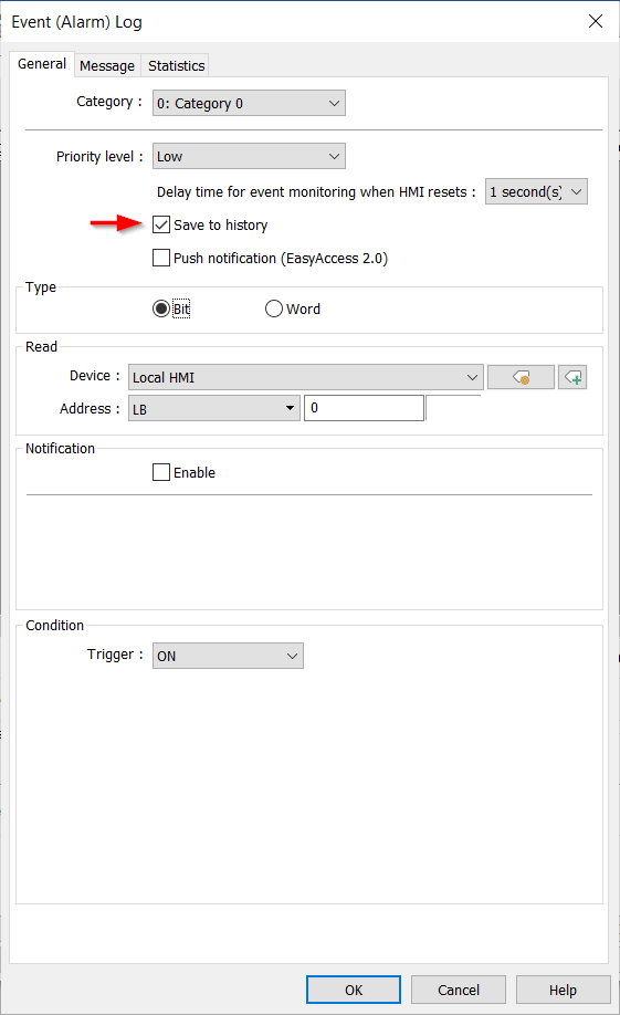
For demonstration purposes, I will define the “Type” as “Bit” and “Read” address “LB-0”. Enable the “Save to history” feature to retain the alarm data:
-
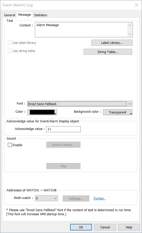
In the “Message” tab, input the desired message to be displayed when the alarm is activate. In this demo, the message will be “Alarm Message”:
-
Next we will set up an “Event Display” object to display the alarm history. This object is located within the “Data/History” tab:
-
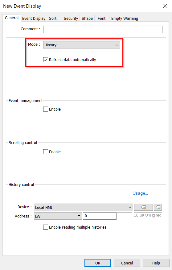
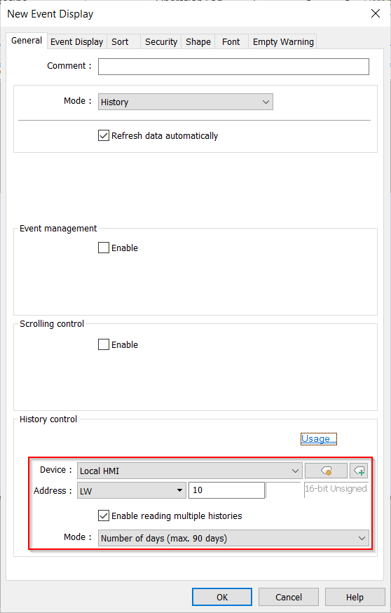
Within the “Event Display,” select “History” as the “Mode” to display all saved alarm history. Alternatively, choose “Real-time” mode to only display current alarms. Enable “Refresh data automatically” for real-time updates:
-
In the “History control” section, we’ve used the HMIs “Local word” address “LW-10” to control what day (by index) the “Event Display” object will display. When “Enable reading multiple histories” is selected, two consecutive addresses are used to define the time-frame. Within this demo, LW-10 will represent the start date, with 0 signifying today, 1 for yesterday, and so forth. Whereas LW-11 will hold the total number of days to display from the start day:
Note: Click the “Usage…” button to learn more about the “History control” address.
-
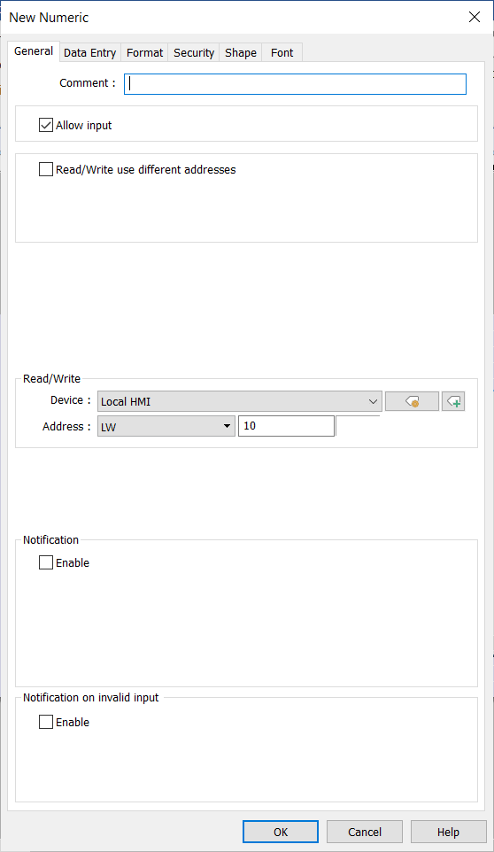
We’ll place the “Event Display” and then create two “Numeric” objects to define the range of alarm data to display. The “Numeric” objects are located within the “Object” tab:
-
Set the “Read/Write” address of the first numeric object to “LW-10” to represent the start date of the event display range. The second numeric object’s address should be set to “LW-11” to determine the total number of days to display:
-
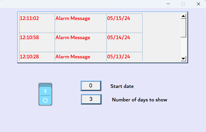
In this example, the “Start date” is set to today, which is 05/15. The “Total days” register is set to 3, indicating that three days’ worth of alarms will be displayed, including today’s alarms within the event display:


Keywords
Keywords: non-cMT, Date, alarm history, event display, numeric objects, preservation, event log, HMI memory, preservation limit, message, bit, iP Series, iE series, eMT, XE,