- HMI Model:MT8052IP
- EasyBuilder Pro Version:6.10.01
Hello, I need to connect a Parker PSD1 drive with an integrated PLC (Codesys) to an MT8052IP display.
Has anyone done this and can help me?
Thanks
Hello, I need to connect a Parker PSD1 drive with an integrated PLC (Codesys) to an MT8052IP display.
Has anyone done this and can help me?
Thanks
Hi @ilbadile,
For a built in Codesys PLC we recommend the Codesys V3 ethernet driver.
All of our PLC connection guides are on our forum, that will walk you through how to set up the connection to your HMI. Below is a link.
https://forum.weintekusa.com/pub/supported-devices
Please let us know if you have any other questions.
Thanks for your reply. Unfortunately, I see that in the Parker section there are no instructions for connecting the PSD1 model, probably because it’s a new model.
I’ll try to see if I can somehow get them to communicate by importing the tags.
Kind Regards
Hi @ilbadile ,
Drivers, components, or controllers that have a CODESYS runtime are usually compatible with the generic CODESYS driver we have. Could you try the driver and see if a connection is successful.
Please let us know if you have any other questions.
Thanks Aaron for your availability.
The new Parker PSD1 drives have an integrated PLC and are programmed with Codesys V3. They have 3 Ethernet ports, 2 of which are configured for the fieldbus, which is also configurable (I use Ethernet/IP). Currently this drive is connected to an Omron CJ2m PLC in Ethernet/IP which I use to read and write 2 dint variables on the drive. This PLC has been configured with the Parker EDS file. I have machines with an old PLC on which I cannot put the Ethernet/IP card. I wanted to use the panel directly to read and write these variables on the drive via Ethernet/IP, i.e. use the panel as a Master instead of the PLC. Is it possible to do this?
Kind Regards
Hi @ilbadile,
Could you confirm if the CODESYS V3 (Ethernet) driver was successful for you? This would allow you to pull tag information for reading and writing, which is not possible with the generic EtherNet/IP drivers.
Thank you!
Hi Aaron,
Unfortunately not. The drive is probably not a standard Codesys , but only the PLC part. The fieldbus configuration is done by an external application provided by Parker “PSD Servo Manager”.
As I mentioned, the drive has 3 ports: 2 for the fieldbus (in -Out) and one dedicated to parameterization using the software I just mentioned.
Kind Regards
Hi @ilbadile ,
To make your Weintek HMI act as the master we recommend trying the ODVA EtherNet IP Explicit Messaging driver or the ODVA General EtherNet IP Implicit Messaging driver to allow for connection.
For details on the correct EtherNet/IP objects, instances, and drive-side configuration, please refer to the Parker PSD1 documentation or contact Parker support. If you run into any issues with the HMI driver settings or tag configuration in EasyBuilder Pro, feel free to reach out to us and we’ll be happy to help.
Thank you!
The drive works, but I can’t figure out how to create the structures.
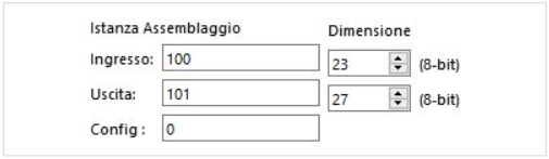
In my case, I have two objects to configure.
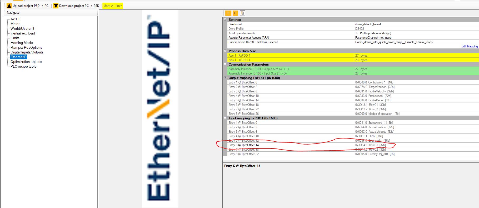
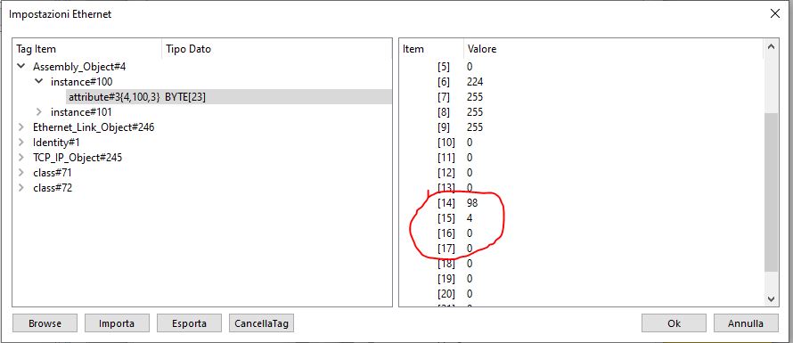
Assembly 100 and Assembly 101, which I receive from Easybuilder as byte arrays (23 for 100 and 27 for 101). For example, how can I tell bytes 14 to 17 to be considered when reading or writing a 32-bit DINT data item?
I can’t find how to create the structures in the Help section. Can you help me?
Kind Regards
PS: Unfortunately, your forum doesn’t allow me to upload screenshots in this reply.
Hi @ilbadile ,
We made updates to the forum and you should be able to post your images now. Could you try again and we will proceed from there.
Thank you!
Hi Aaron
Thank you for your time.
As I was saying, in the Parker Manager tools, you can set the tags to be made available.
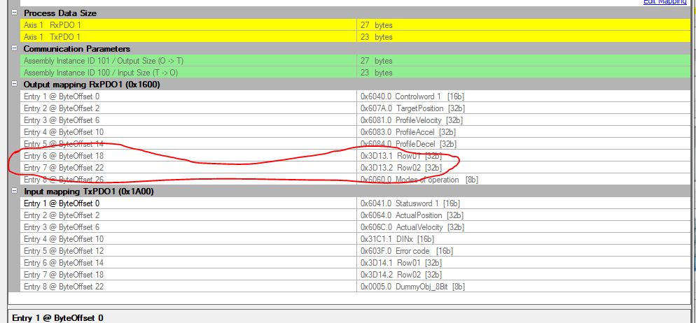
Some are predefined, others (Row01 and Row02) are containers for user variables that I can map both as a value and a size.
In my case, I mapped the Row01 input as a DINT in Assembly 100.
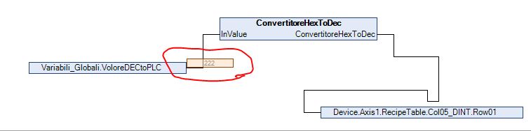
The ROW in turn have columns where I write the value based on the size of the data. In my case the value I need is a DINT that I write by converting it from hexadecimal to decimal in codesys for process reasons related to other needs .In the following example I send the value in codesys program 222 Hex converted to decimal = 546 to Row01.Col05Dint
in the parker manager in online mode i see the value.
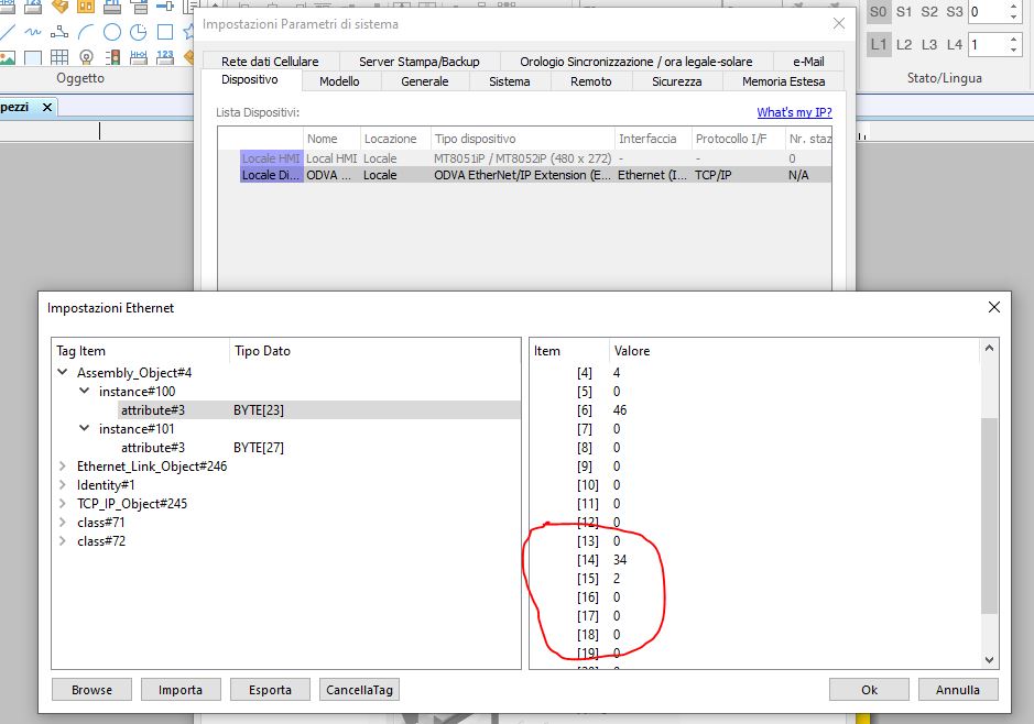
in EasyBuilder i see the Value but it’s an array of Byte
My requirement is to display the value in Hex on your HMI, which in my example is 222.
And to be able to write a number in another variable that will be written on the display in decimal but sent to the row in Hex.
Is it possible?
P.s Unfortunately some of our old PLCs do not support ethernet/IP (more than 400 units) and for this reason for these I have to mount your HMI to read and write the quota of an electric axis of this application. For the Omron CJ2M PLC that supports Ethernet/IP, I just create the network and map a DINT variable on my PLC and everything works.
Thanks
Kind Regards
Hi @ilbadile,
We would recommend using the ODVA General EtherNet IP Implicit Messaging driver as it would allow you to easily combine bytes in order to form INT or DINT values. Can you please try using this driver instead of the extension driver and let us know if you are able to establish communication?
Hi Brendon
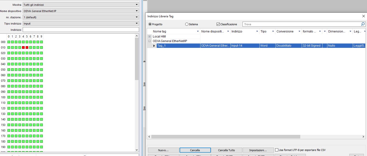
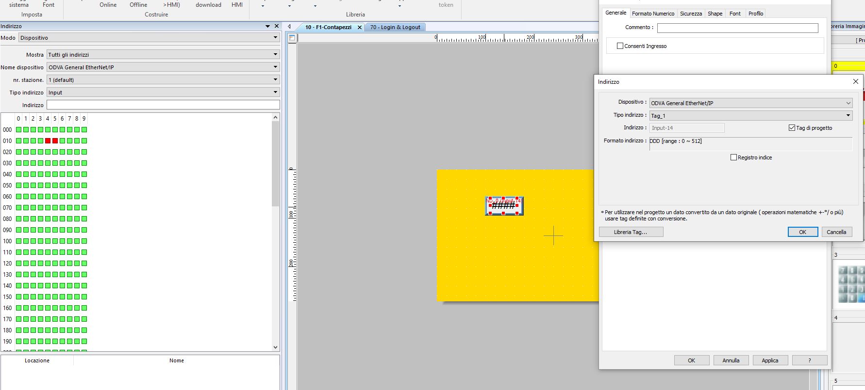
I tried to set it up and create a Tag but it tells me it can’t connect to the drive
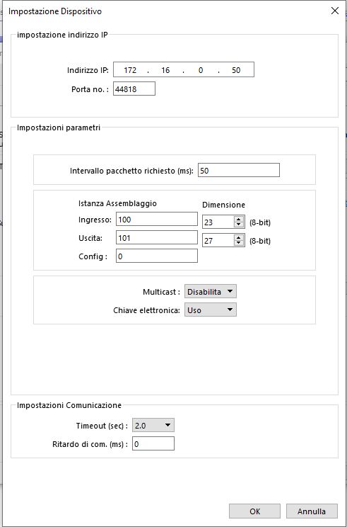
and mapping a tag in this mode
and apply in this mode
But it not work “Device Not Respond”
Kind regards
Hi @ilbadile,
Is it possible that the input and output instance numbers are in the correct order? This information can usually be determined by reading the EDS file directly.
If you a still unable to communicate while using this driver, I would recommend that you try the following:
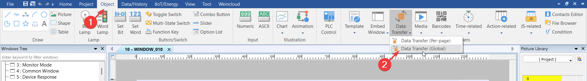
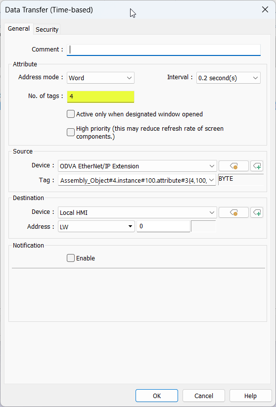
Use the “ODVA…Extension” driver as in your previous image:
Within the “Object” tab select “Data Transfer (Global)”:
Within the “Time-based” tab create a new transfer and transfer the 4 tags that comprise your DINT value into an LW register:
Click “Ok” when finished.
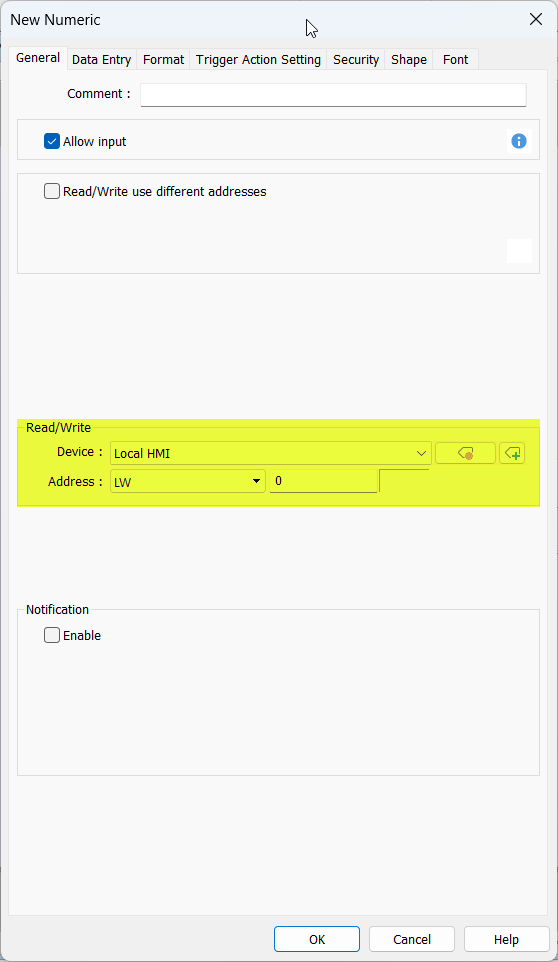
Create a “Numeric” object addressed to the LW register used in step 3:
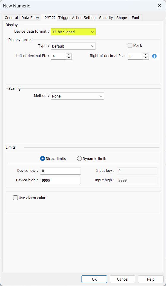
Ensure that the “Device data format” set within the "Format’ tab is 32-bit signed or unsigned depending on the expected value:
Hi Brendon,
It finally works! Thanks for your support.
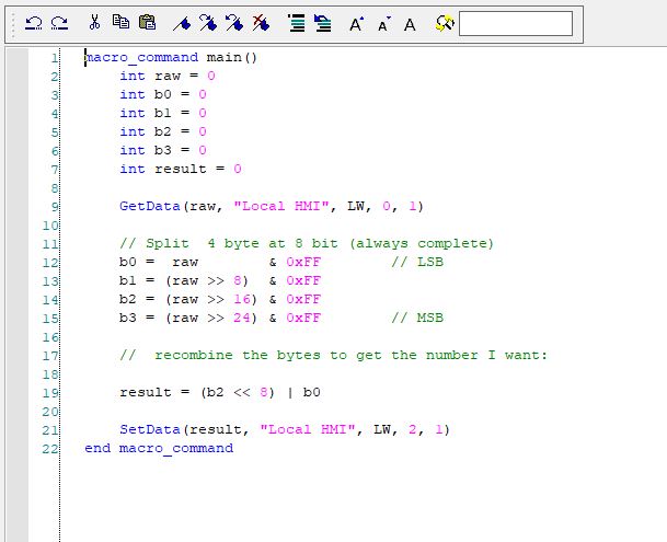
The only thing I had to add is a macro that splits the word into 4 bytes.
I share my experience if there is any other user who has this need for PSD drives.
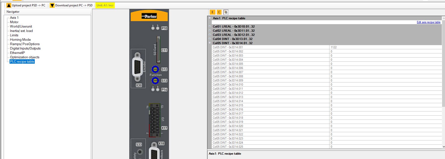
In Parker Manager, in the assembly 100 I need to read is 32-bit (from byte 14 to 17, which correspond to the user rows, see photo above). In the software, there are columns for these rows where, via Codesys, you can read or write data based on the column you choose. The format is different (DINT, LREAL, etc.).
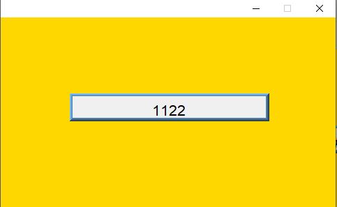
which as you can see now is 1122, on Easy builder on byte 14 and 15 there is the value split into bytes.
If I send it directly into the 2 words(from 14 to 17 bytes 32Bit) LW0-1 needed to contain the 32 bits the result was:
00000000-00000100-00000000-01100010=262242
the second and fourth bytes are 4 and 98 respectively which when put together give the correct value 1122
01100010=98
00000100=4
01001100010=1122
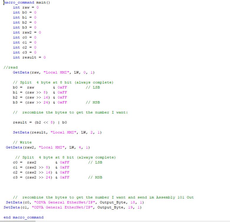
To combine it in the correct way I made a macro that divides the values loaded on LW0-1 into 4 bytes and puts them combined in the correct way on LW2
And so it works perfectly.
Thanks again for your support. If you have any suggestions on how to do things differently, they’re welcome.
Kind Regards
Hi @ilbadile,
Thank you so much for sharing your solution! Have a great day!
Hi Brendon,
Today I tried writing with the same method in various ways, but it doesn’t let me write at all. Do you have any suggestions?
The Assembly out it’s 101 27 Byte the raing
The field is similar to the IN but it goes from 18 to 22 I have tried in a thousand ways but it does not write from the panel while if I use the PLC it does
Kind Regards
If you try to change the value of just ByteOffset 18 using a numeric object will the drive reflect that change?
Hi Brendon,
Today i’ve solved this last issue .
Now it work (read -Write)
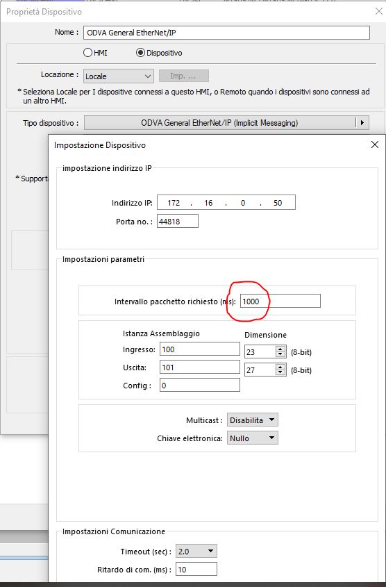
I used the same system to read (with the Macro) but I changed the communication protocol in this mode.
The speed must be set to 1000ms as in the EDS file, otherwise the drive will go into alarm**.**
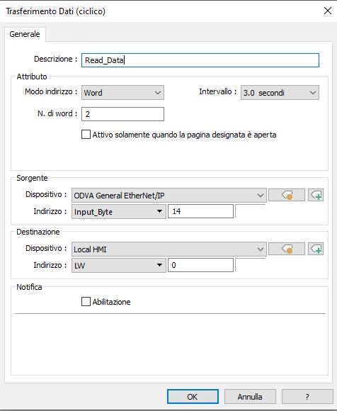
In the global data transfer field I changed the tag to input_byte which transfers the data that will go to LW0 managed by the macro
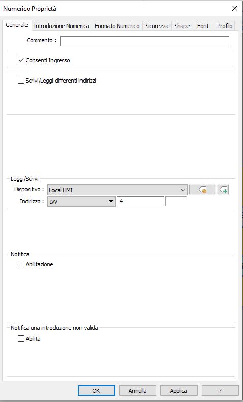
I created a new input field
And set it up like this.
Relying on the word LW4 that I will use in the macro
The writing part is added to the macro
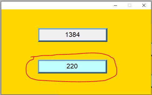
It works perfectly.
Thanks again
Kind Regards
Hi @ilbadile,
That’s great news, thank you again for posting your solution!