Introduction:
When a device does not support a standard industrial protocol like Modbus or if EasyBuilder Pro does not have a driver suitable for the target device, the “Free Protocol” driver may be used to facilitate communication. This driver allows the user to design a custom payload for the target device to issue commands or to receive and parse a response. Within this post we discuss the basics of our “Free Protocol” driver and demonstrate how to send and receive device data.
Contents:
Software Version:
EasyBuilder Pro 6.03.02.393+
Instructions:
Driver setup:
-
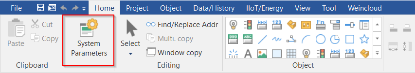
To add the “Free Protocol” driver, select the “Home” tab and open the “System Parameters”:
-
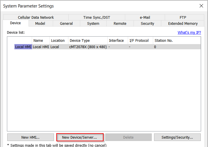
Within the “System Parameters” select “New Device/Server…”:
-
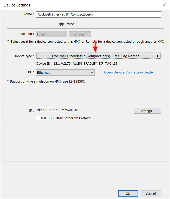
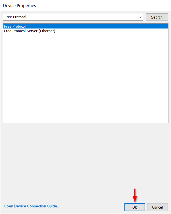
Click the center of the “Device type” drop-down list to search for the “Free Protocol” driver:
-
Once found, click “Ok”:
-
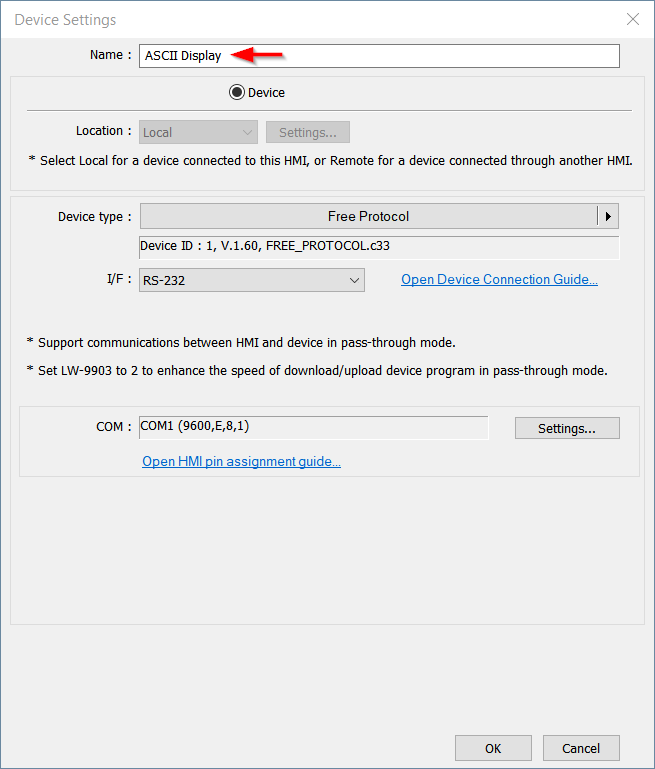
Assign a unique name to this device:
-
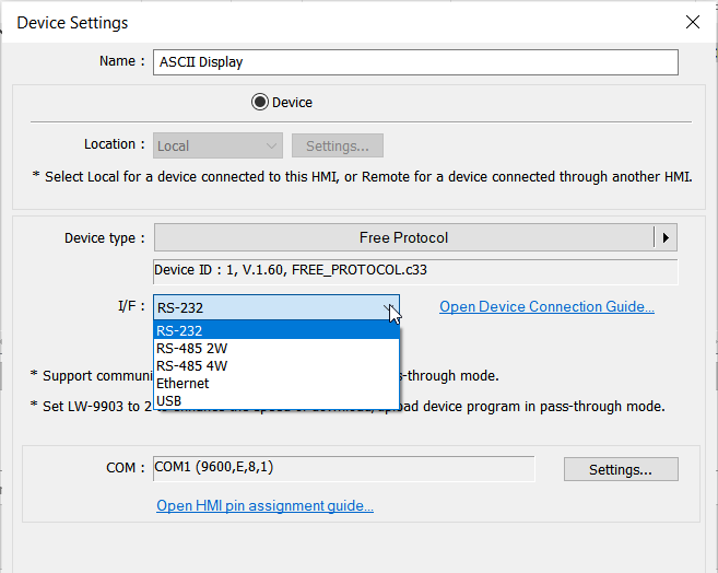
Select the desired interface using the “I/F” drop-down list:
Note: When using a serial interface, it may be necessary to select a compatible “COM” port within the “Settings…” menu first.
-
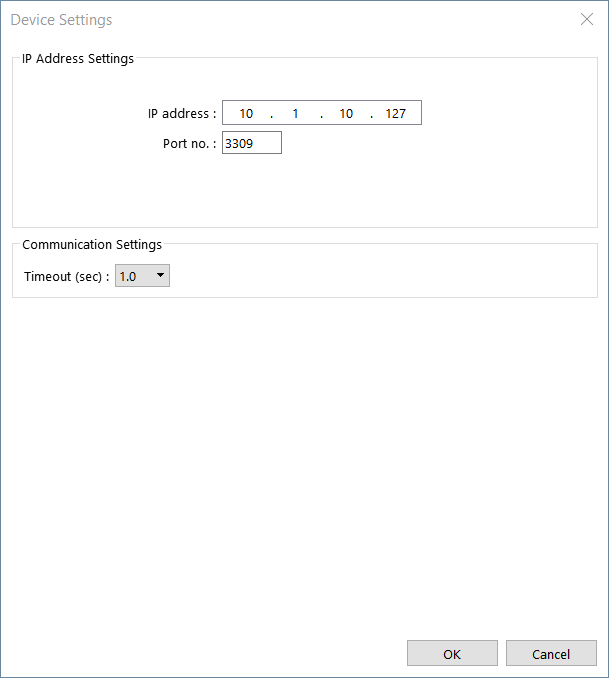
Click “Settings…” to define the desired communication parameters:
-
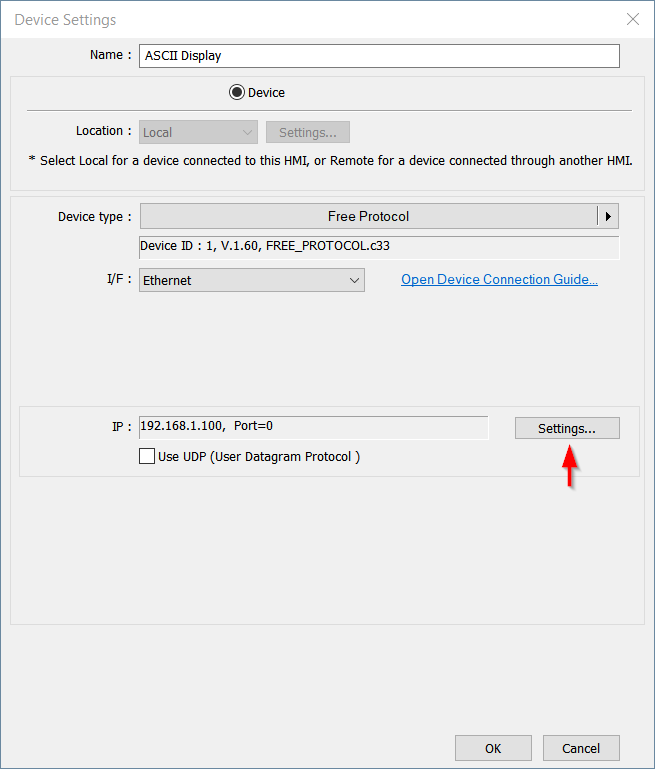
When using an “Ethernet” interface, the communication “Port” may be specified within the user manual of the external device, or it may be user-defined with 3rd party software. The “IP address” is the IP of the external device not the HMI:
Note: As an example, the standard Modbus TCP/IP port is 502 but some vendors use 5020. If need be, please consult the device vendor for clarification.
Tip: Within the device manual, search for keywords like “TCP” or “Port” or “Interface”.
-
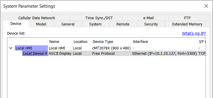
Click “Ok” to add this device to your device list:
Background
Before we, send a command we must understand the required payload format. The external device is unlikely to perform the desired action if we make a mistake. So, at this point we should refer to the device manual to understand the command structure. Some devices may support simple ASCII commands like %START \r whereas others may require you to format an array of bytes in a specific way. I have added a few examples below:
| Format | Example | Macro |
|---|---|---|
| ASCII | %START \r | char cmd[7] = "%START" // declares a byte array initialized // to %START cmd[6] = 0x0d // assigns the carriage return to the last element // of the array |
| Struct. (bytes) |
[0] Unit ID [1] Length [2] Command [3 +] Data |
char cmd[15]// declares a byte array without initialization cmd[0] = 0x01 // defines the target unit ID as '1' cmd[1] = 0x0c // defines the length of data cmd[2] = 0x06 // defines the command // Data defined here and below |
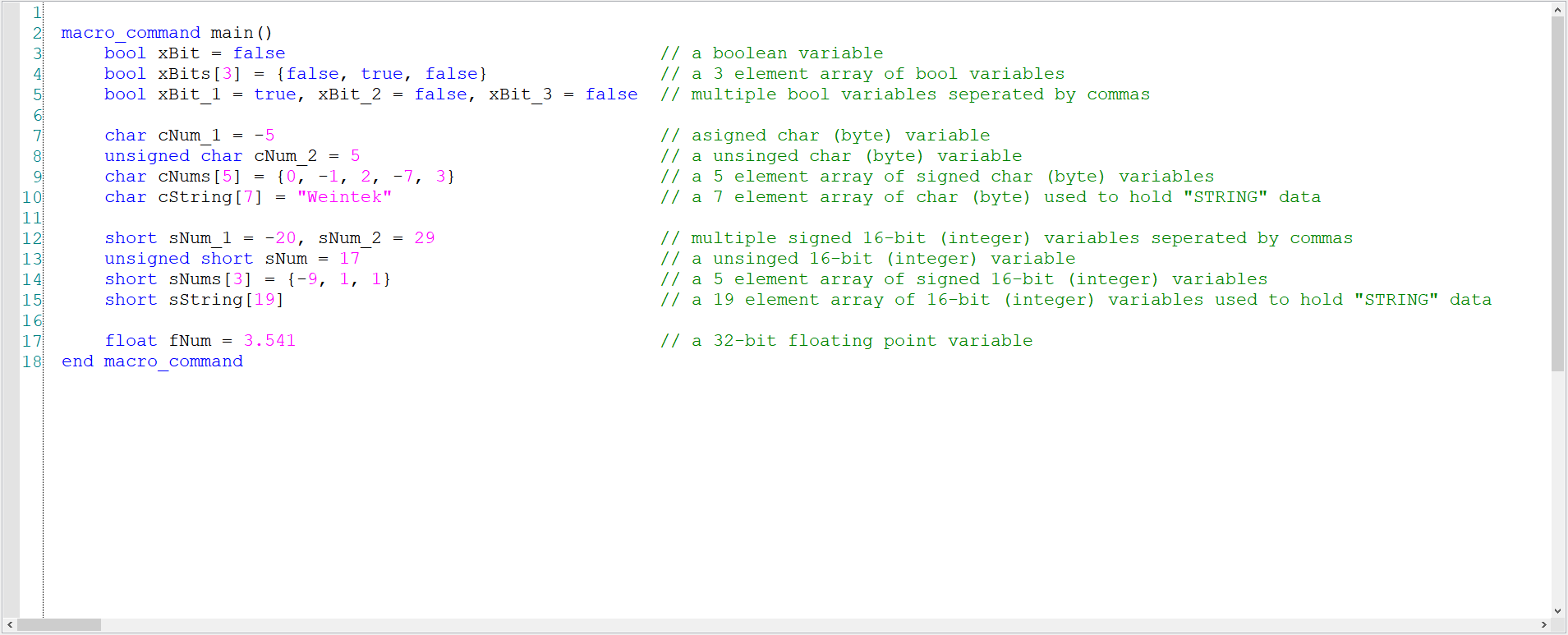
If you are not familiar with our Macro workspace, please note that Macros support the following data types:
| Declaration | Type | Equivalent | Range | |
|---|---|---|---|---|
| bool | bit | BOOLEAN | 0 ~ 1 | |
| char | byte (signed) | SINT | -128 ~ 127 | Note 2 |
| short | 16-bit (signed) | INT/WORD | -32768 ~ 32767 | Note 2 |
| int | 32-bit (signed) | DINT/DWORD | -2147483648 ~ 2147483647 | |
| float | 32-bit (float) | REAL | ||
| unsigned char | byte (unsigned) | USINT | 0 ~ 255 | |
| unsigned short | 16-bit (unsigned) | UINT | 0 ~ 65535 | |
| unsigned int | UDINT | 0 ~ 4,294,967,295 | ||
| long | LINT | -248 ~ 248 | Note 1 | |
| unsigned long | ULINT | 0 ~ 248 | Note 1 | |
| double | LREAL | -248 ~ 248 | Note 1 |
Note 1: See appendix D [Link] for information related to the limitations of 64-bit support.
Note 2: A char array is used to represent STRING data in register-based PLCs. A short array is used o represent STRING data in certain tag-based PLCs.
Note 3: An array is declared using the [ ] operator as in type variable[#] or char data[16].
Within the “ASCII” example, a character sequence defined as \r was displayed. This character represents what is called a “carriage return”. This is a non-readable character used to indicate or terminate the command sequence. When analyzing the device specifications, it is important to consider that a sequence defined as \r or CR is likely not a readable character. In fact, certain vendors may define these “characters” in other ways and as such it is important to review online sources to determine the corresponding ASCII code as in:
| Character | Dex | Hex |
|---|---|---|
| Null | 0 | 00 |
| Start of heading (SOH) | 1 | 01 |
| Start of text (STX) | 2 | 02 |
| End of text (ETX) | 3 | 03 |
| End of transmission (EOT) | 4 | 04 |
| End of query (ENQ) | 5 | 05 |
| Acknowledge (ACK) | 6 | 06 |
| Beep (BEL) | 7 | 07 |
| Backspace (BS) | 8 | 08 |
| Horizontal Tab (HT) | 9 | 09 |
| Line feed (LF) | 10 | 0a |
| Vertical tab (VT) | 11 | 0b |
| FF (FORM FEED) | 12 | 0c |
| CR (CARRIAGE RETURN) | 13 | 0d |
| SO (SHIFT OUT) | 14 | 0e |
| SI (SHIFT IN) | 15 | 0f |
Sending a command:
Note: Within this demonstration, we will design a macro to send data according to the sample structure defined below.
| Format | Example | Macro |
|---|---|---|
| Struct. (bytes) |
[0] Unit ID [1] Length [2] Command [3 +] Data |
char cmd[15]// declares a byte array without initialization cmd[0] = 0x01 // defines the target unit ID as '1' cmd[1] = 0x0c // defines the length of data cmd[2] = 0x06 // defines the command // Data defined here and below |
-
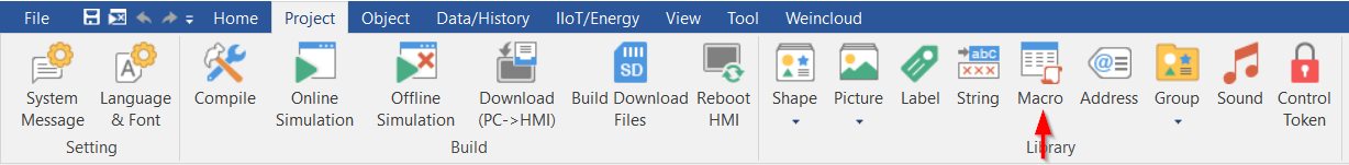
To send data to a device using the “Free Protocol” driver, select the “Project” tab and click “Macro”:
-
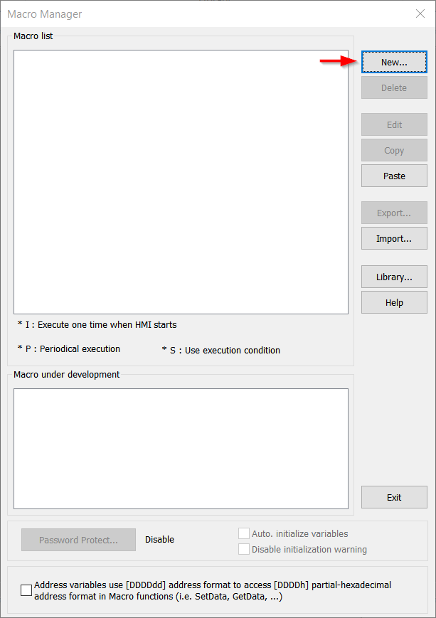
Within the following menu, click “New” to create a new Macro:
-
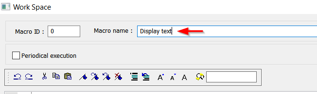
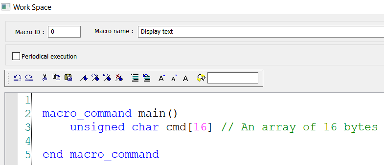
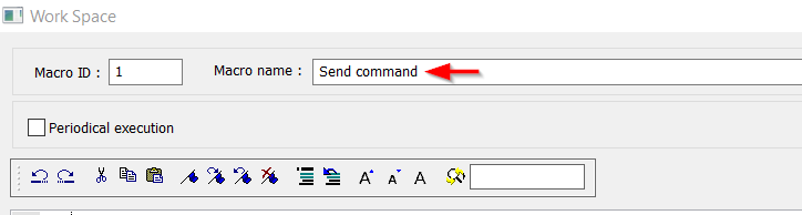
Define the “Macro name”:
-
Declare a ‘char’ array with a length equivalent to that of the expected payload:
-
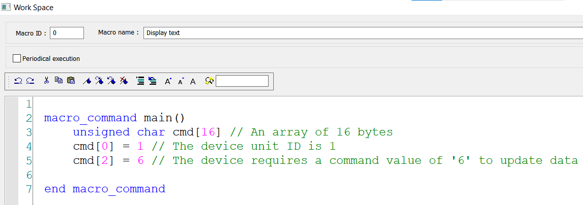
Assign values to array elements as needed:
Note: I did not define the length because we have not determined how much data we want to send.
-
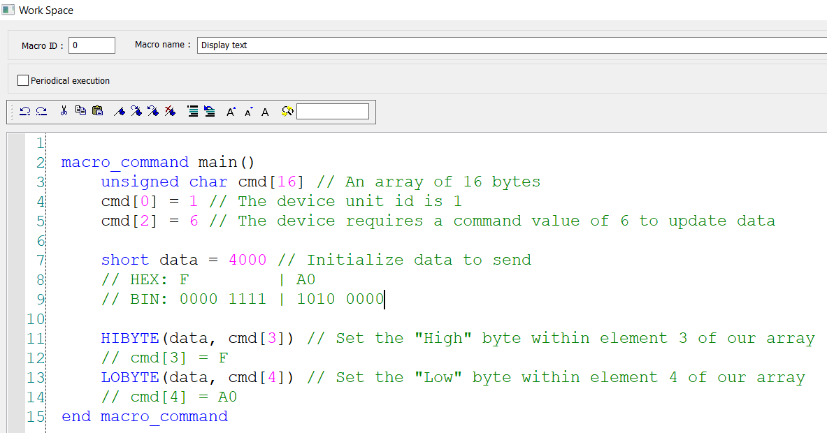
Since the example format specifies that byte element 3+ will hold our data, we need to arrange the “data” portion of our byte array in a manner that the device can interpret. This is often referred to as endianness and a device may be said to be either big-endian or little-endian as in the example below:
Note: Endianness determines the byte order. In little-endian byte ordering, the least significant byte (LSB) is stored first. In big-endian byte ordering, the most significant byte (MSB) is stored first. The example below refers to the hexadecimal numbers 0x1234 and 0x12345678.
| Endian: | Big | Little | |
|---|---|---|---|
| MSB | LSB | ||
| 0x12 | 0x34 | 0x34 | 0x12 | ||
| 0x12 | 0x34 | 0x56 | 0x78 | 0x78 | 0x56 | 0x34 | 0x12 |
-
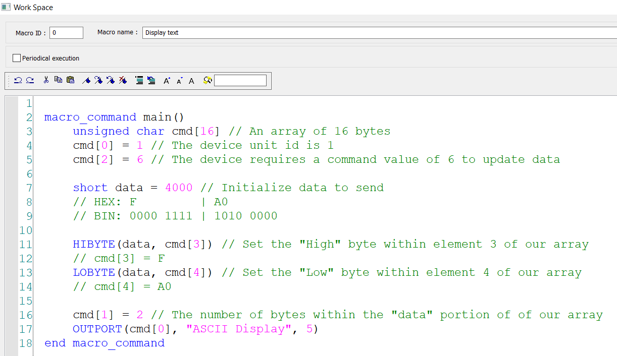
To send a 16-bit value of 4,000 in big-endian format we can use the HIBYTE() and LOBYTE() functions to extract each byte. The parameters required by these functions are ‘source’ and ‘result’, as in HIBYTE(source, result). Within the example below, we use these functions according to the “endian” requirements of the target device:
Note: The big-endian hexadecimal format of4000is0xFA0as the most significant byte0x0Fis ordered first.
-
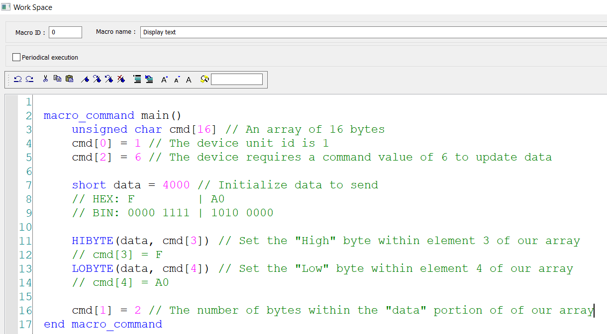
According to the example payload format, we must also define the byte length, which we now know is ‘2’ according to this example. Within the example below, we set the “length” element of our array:
-
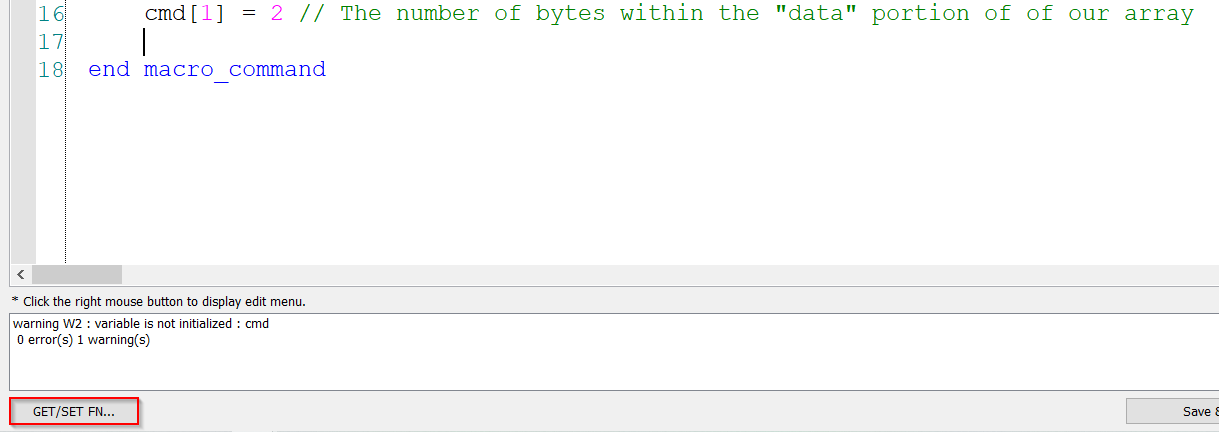
To send this data to the target device, move your cursor to a new line and select the “GET/SET FN…” button:
-
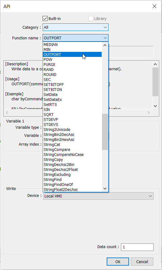
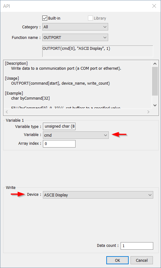
Within the “API” dialog, select the “OUTPORT” function from the function name drop-down list:
-
Select the variable or byte array that you would like to send and ensure that the “Free protocol” device is selected within the “Write” section:
-
The “Data count” may be dynamic depending on the source of data, but in this case the total number of bytes that we would like to send is ‘5’:
-
Click “Ok” to add this function to your macro:
Note: The “OUTPORT” function is used to send data of a specified length to a target device.
-
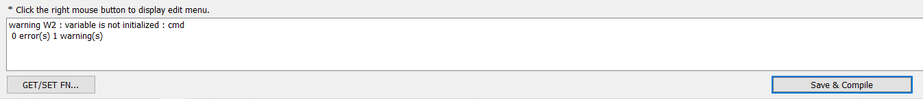
Click “Save & Compile” to verify that your code is error free:
-
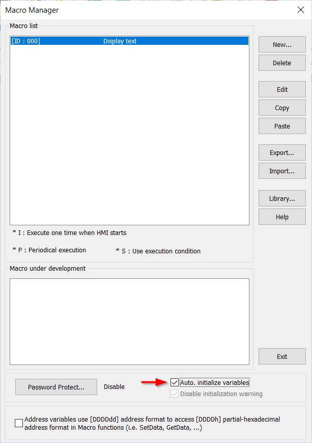
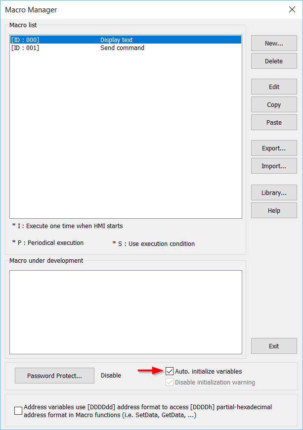
Within the “Macro manager” ensure that “Auto. initialize variables” is enabled:

Sending ASCII data:
Note: Within this demonstration, we will design a macro to send data according to the sample structure defined below.
| Format | Example | Macro |
|---|---|---|
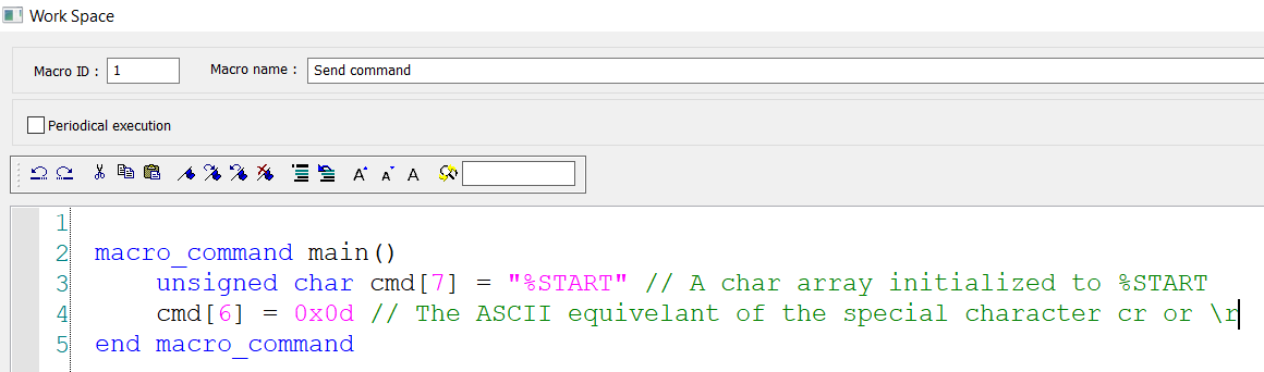
| ASCII | %START \r | char cmd[7] = "%START" // declares a byte array initialized // to %START cmd[6] = 0x0d // assigns the carriage return to the last element // of the array |
-
To send data to a device using the “Free Protocol” driver, select the “Project” tab and click “Macro”:
-
Within the following menu, click “New” to create a new Macro:
-
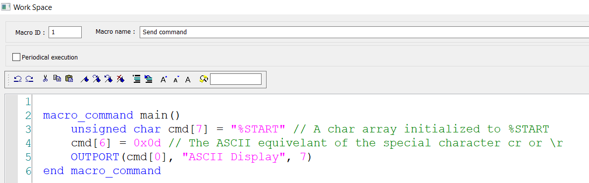
Define the “Macro name”:
-
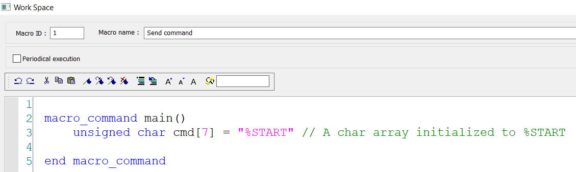
Declare a ‘char’ array with a length equivalent to that of the expected payload:
Note: This char array has 7 elements, but %START is only 6 characters. The device requires a special character ‘\r’ to terminate the sequence. We will add this on the following line using its ASCII code.
-
Define any required special characters:
-
To send this data to the target device, move your cursor to a new line and select the “GET/SET FN…” button:
-
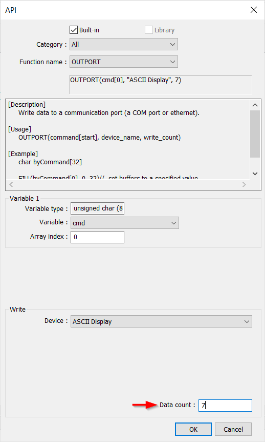
Within the “API” dialog, select the “OUTPORT” function from the function name drop-down list:
-
Select the array that you would like to send and ensure that the “Free protocol” device is selected within the “Write” section:
-
The “Data count” may be dynamic depending on the source of data, but in this case the total number of bytes that we would like to send is ‘7’:
-
Click “Ok” to add this function to your macro:
Note: The “OUTPORT” function is used to send data of a specified length to a target device.
-
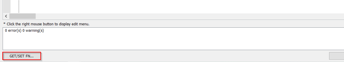
Click “Save & Compile” to verify that your code is error free:
-
Within the “Macro manager” ensure that “Auto. initialize variables” is enabled:
Reading device data:
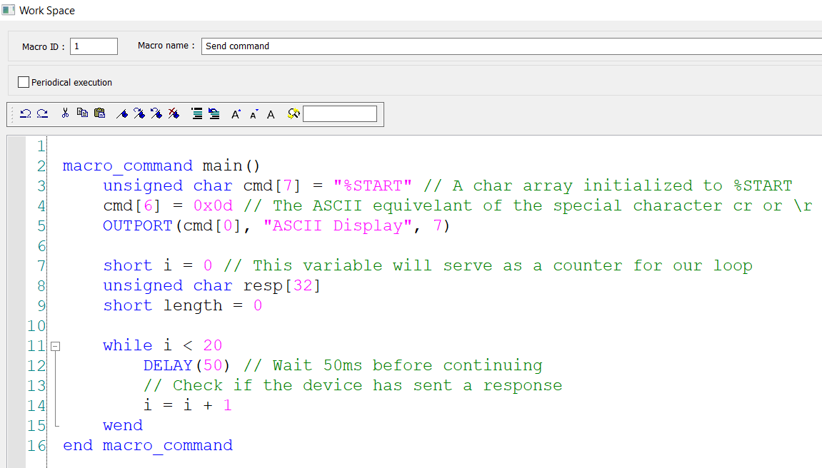
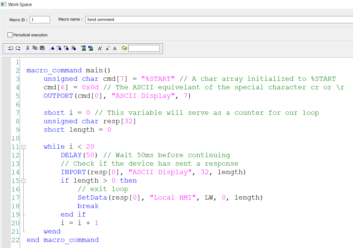
Note: Within this demonstration, we will revise the macro within “Sending ASCII data” to read a value returned by the device as a response to the command below.
| Format | Example | Macro |
|---|---|---|
| ASCII | %START \r | char cmd[7] = "%START" // declares a byte array initialized // to %START cmd[6] = 0x0d // assigns the carriage return to the last element // of the array |
-
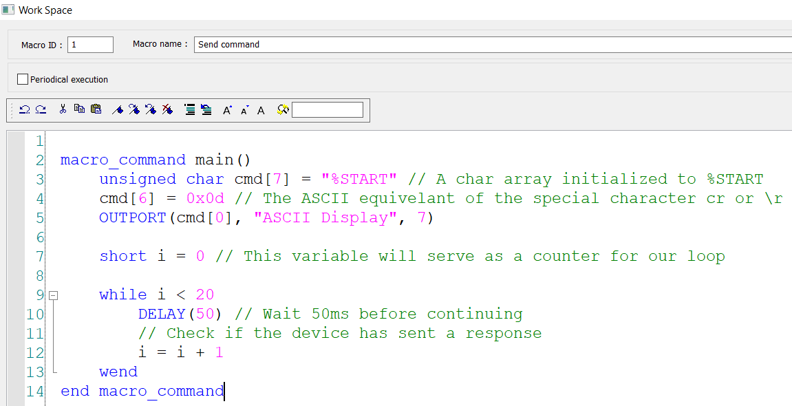
After sending a command using the “OUTPORT” function, the device may take some time to respond. The response delay depends on how data is handled by the target device as well as the interface type and configuration. To account for this delay, I recommend using a DELAY() function within a “while” loop as in the example below:
Note: This method will allow you to define a dynamic timeout based ondelay x loop. We expect that the device will respond faster than the loops maximum value multiplied by the delay time, which in this case is 1s. However, if the device does not respond within 1s, we may consider the device offline. If we do not use this method and choose an arbitrary delay or no delay at all, there is a chance that we may attempt a “read” before the device actually sends a response.
-
In order to record the response, we will need to declare another char array to hold received data as well as a short integer to determine receive length:
Note: I have added these variables on lines 8 and 9 below.
-
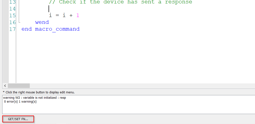
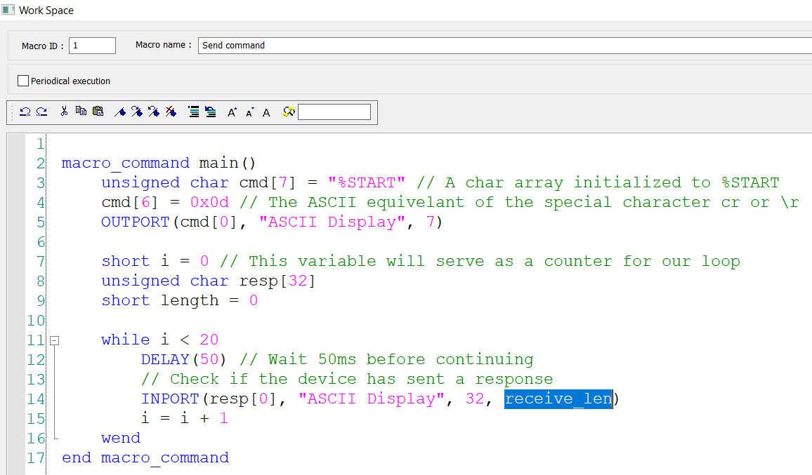
To read data from this device we will use an “INPORT” statement. I will move my cursor to a new line within the ‘while’ loop and select the “GET/SET FN…” button to declare this function:
-
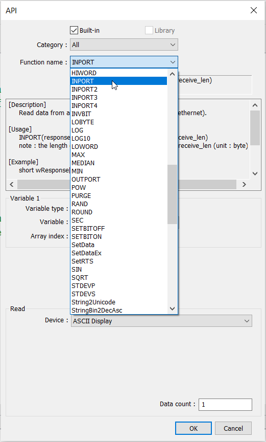
Within the “API” dialog, select the “INPORT” function from the function name drop-down list:
-
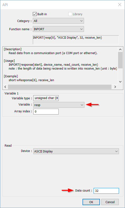
Select the byte array that you’ve created to hold the response and ensure that the “Free protocol” device is selected within the “Read” section and that the “Data count” matches the array length of the “response” variable:
-
Click “Ok” to add this function to your macro:
-
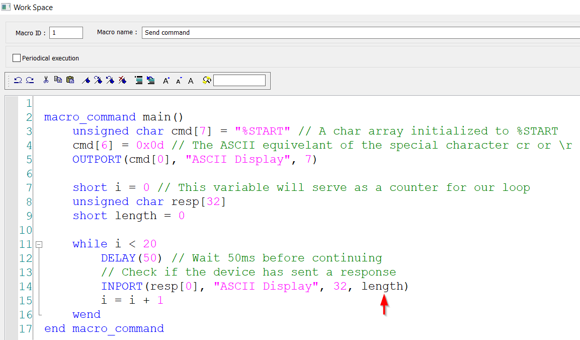
Replace the “receive_len” variable (above) with the “length” variable that you declared in step 2:
-
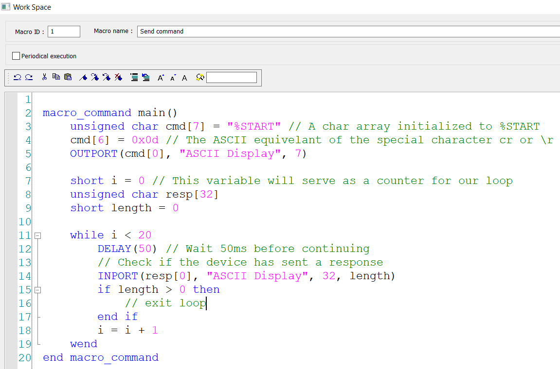
Below the “INPORT” function, use an “if” statement to check if the recieve_len or “length” variable is greater than 0. This will allow us to determine when we’ve received a response:
-
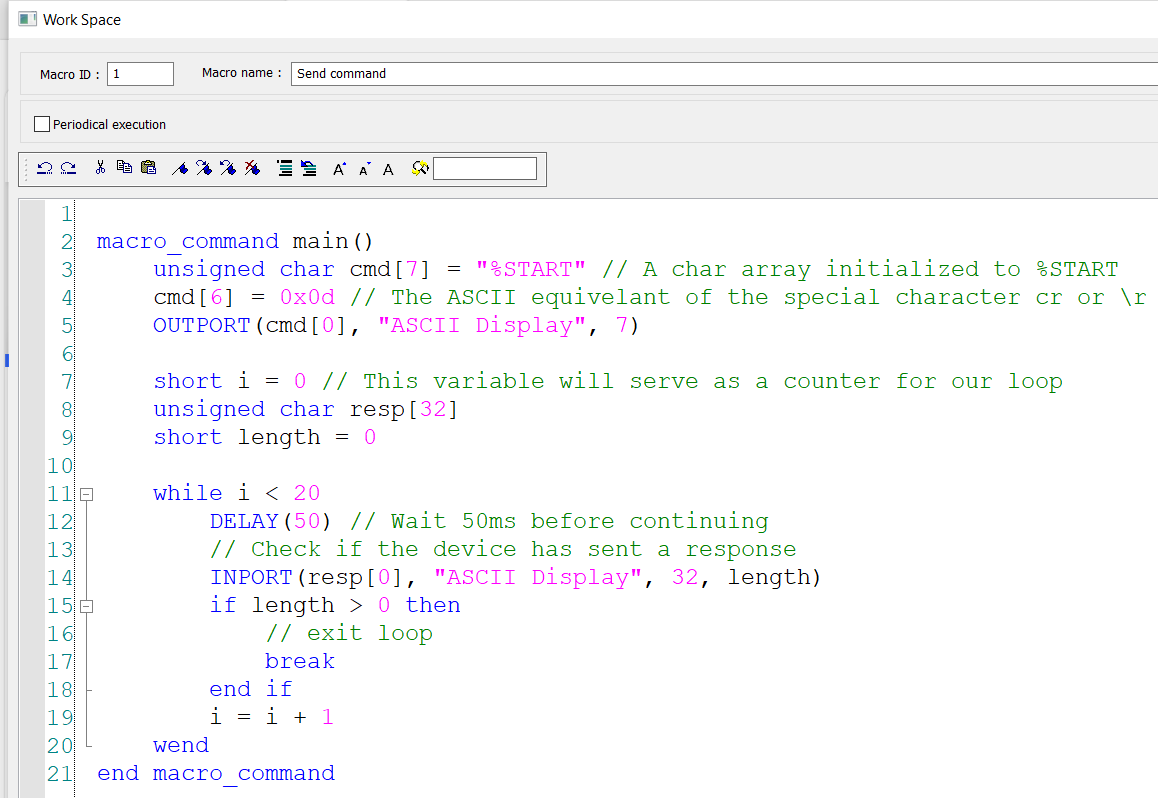
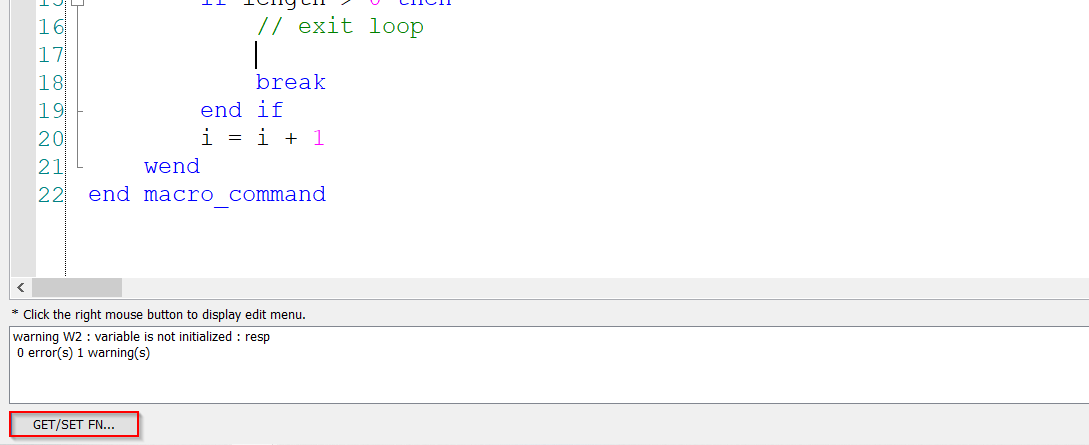
To exit the loop when a response is received, we will use a “break” statement as on line 17:
-
While “breaking” the loop, we can display our response data by “setting” it within HMI memory. To do this, move your cursor to a new line above the “break” statement and select the “GET / SET FN…” button to open the API:
-
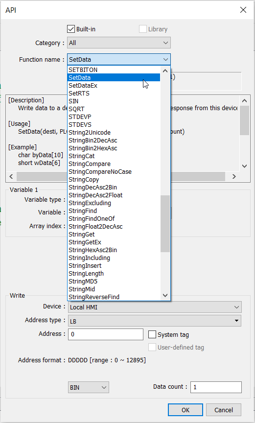
Within the “Function name” drop-down list select “SetData”:
-
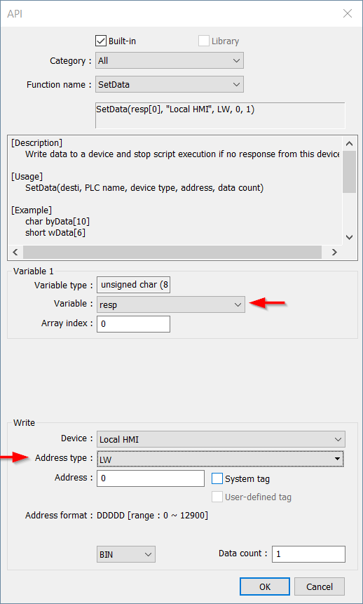
Select the “response” variable within “Variable” drop-down list and choose an available region within LW memory:
Note: The “Data count” is based on the value of the “length” variable. We will replace the default value of ‘1’ after adding the function to our macro.
-
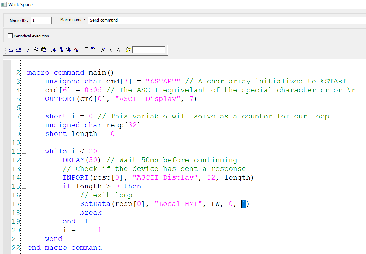
The “Data count” is the last parameter within this function:
-
To display a dynamic data count based on the return length, please replace the default value of ‘1’ with your “length” variable:
-
Within the “Macro manager” ensure that “Auto. initialize variables” is enabled:
Tips:
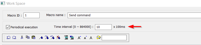
- Use “periodical execution” to send a request or read a response cyclically:
Note: The macro may take longer than the defined interval to execute, depending on the time required to execute the functions within.