Digital IO:
| Parameter | Sub-parameter | Definition | Options |
|---|---|---|---|
| Output value parameter On error | Output behavior On error | This parameter determines how the IO module will behave when communication between the iR-ECAT and controller is severed. Note: The format of this parameter is decimal, but we must consider it’s binary representation in order to determine what channels are configured. |
0: Keep last output value 1: Use “Substitute Value 0” |
| Output value parameter On error | Substitute Value 0 | This parameter determines what value will be used as an output when communication between the iR-ECAT and controller is severed and a channel is configured to use “Substitute Value 0”. Note: The format of this parameter is decimal, but we must consider it’s binary representation in order to determine what channels are configured. |
0: False 1: True |
Example:
| Sub-parameter | Setting | Equivalency | Result |
|---|---|---|---|
| Output behavior On error | 240 | 1111 0000 | Outputs 4 ~ 7 use a substitute value Outputs 0 ~ 3 retain the most recent output value |
| Substitute Value 0 | 192 | 1100 0000 | Outputs 6 ~ 7 have a substitute value of true Outputs 0 ~ 5 have a substitute value of false |
| Output behavior On error | 2 | 0000 0010 | Output 1 uses a substitute value Outputs 0 and 2 ~ 7 retain the most recent output value |
| Substitute Value 0 | 2 | 0000 0010 | Output 1 has a substitute value of true Outputs 0 and 2 ~ 7 have a substitute value of false |
| Output behavior On error | 255 | 1111 1111 | Outputs 0 ~ 7 use a substitute value |
| Substitute Value 0 | 15 | 0000 1111 | Outputs 0 ~ 3 have a substitute value of true Outputs 4 ~ 7 have a substitute value of false |
Note:
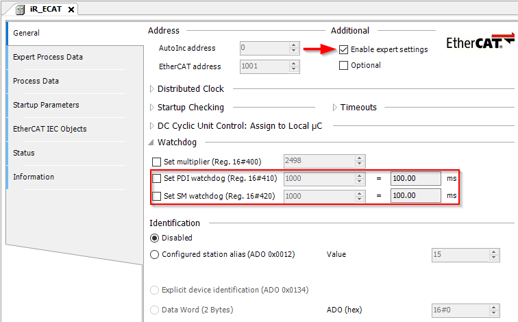
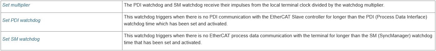
- To adjust the response time of the “Output value parameter On error”, please adjust the watchdog settings of the iR-ECAT:
- These parameters are described in detail within the image below:
Analog IO:
| Sub-parameter | Definition | Options |
|---|---|---|
| Output Mode | The analog output mode may be set by entering an appropriate decimal value. | 0. Close 1. ±10V 2. ±5V 3. 1-5V 4. ±20mA 5. 4-20mA |
| Output Scale Range Upper Limit | The module will convert user input such that the high limit of the selected “Output mode” will equate with this value. (e.g., If the Output mode is ±10V and the current output value is equal to the value within this register, the corresponding channel will output 10V.) |
-32768~32767 |
| Output Scale Range Lower Limit | The module will convert user input such that the low limit of the selected “Output mode” will equate with this value. (e.g., If the Output mode is ±10V and the current output value is equal to the value within this register, the corresponding channel will output -10V.) |
-32768~32767 |
| Update Time | This parameter will allow the module to gradually increase or decrease output thereby serving as a “soft start”. (e.g., If the update time is set to 200 and you configure the module to increase output by 4V the module will increase output gradually over 200 x 10ms = 2000ms, resulting in an increase of 2V per second.) |
Disabled: 0 Enabled: 1~3200 |
| Error Code | An error code is defined by the bits within this parameter according to the list below. | |
0: Analog power low voltage 1: Hardware error 2: Not calibrated 4: Analog conversion error 6: Analog hardware error 8: Input ch.0 error 9: Input ch.1 error 10: Input ch.2 error 11: Input ch.3 error 12: Output ch.0 error 13: Output ch.1 error 14: Output ch.2 error 15: Output ch.3 error |
||
| Command | A command may be used to restore factory settings or reset retained minimum and maximum values. | See “iR-AQ04-VI, iR-AM06-VI, & iR-AI04-VI User Manual” |
| Conversion time | The module requires sufficient time to convert input into engineering units that correspond with the upper a lower limit. This default conversion time per channel is 2ms. The total required conversion time is calculated by multiplying 2ms by the number of channels, for example, input from 4 channels will take 8ms to convert. In fast conversion mode, where only one channel is used, the conversion time can be reduced to 500µs. Setting a lower conversion rate can effectively filter noise in certain environments. | 0. 2ms 1. 2ms 2. 5ms 3. 10ms 4. 15ms 5. 25ms 6. 60ms 7. 0.5ms (Fast Conversion Mode) |
| Input Mode | An analog input mode may be set by entering an appropriate decimal value. Note: See iR-AI04-TR user manual for information pertaining to thermocouple and RTD input modes. |
0. Close 1. ±10V 2. ±5V 3. 1-5V 4. ±20mA 5. 4-20mA |
| Input Scale Range Upper Limit | The module will convert the current input such that the high limit of the selected “Input mode” will equate with this value. (e.g., If the Input mode is ±10V and the current input is 10V, the register associated with this channel will display the value set within this parameter.) |
-32768~32767 |
| Input Scale Range Lower Limit | The module will convert the current input such that the low limit of the selected “Input mode” will equate with this value. (e.g., If the Input mode is ±10V and the current input is -10V, the register associated with this channel will display the value set within this parameter.) |
-32768~32767 |
| Filter Frame Size | The Filter Frame Size can stabilize the signal by averaging sampled values. This parameter specifies the number of samples to average. | Disable: 0 Enabled: 1~20 |
| Output behavior On error | This parameter determines how the IO module will behave when communication between the iR-ECAT and controller is severed. Note: The format of this parameter is decimal, but we must consider it’s binary representation in order to determine what channels are configured. |
0: Keep last output value 1: Use “Substitute Value” |
| Substitute Value | This parameter determines what value will be used as an output when communication between the iR-ECAT and controller is severed and a channel is configured to use “Substitute Value”. | -32768~32767 |