I previously used a cmt-SVR-100 for protocol conversion MODBUS RTU (Zero-based Addressing) to EtherNet/IP (CompactLogix). Now a customer would like MODBUS RTU to MODBUS TCP/IP (Aveva Intouch HMI-SCADA). The SCADA device will only be reading the MODBUS TCP/IP data. I assume I would select MODBUS TCP/IP (Zero based Addressing) in the new Local Device for device type for SCADA? Are there any other questions I should be asking the customer regarding their communication protocol? They did mention “no Gateway” will be used and they have yet to determine an IP address at this time. Thank you.
Would you have any sample programming links for the Macro regarding SetData (I will be using the same GetData Macros as before)?
They should ask if the SCADA system is going to function as a Modbus TCP server or a Modbus TCP client. If the SCADA system will function as a Modbus TCP server, they can use the “Modbus TCP/IP” driver. However, if the SCADA system is going to function as a Modbus TCP client, they should use the “Modbus server” driver within the HMI project.
Here is an example in which the hmi acts as a Modbus tcp server to make Modbus rtu data available to a client.
You will not need to use SetData/GetData. The cMTSVR lets you set up a simple table. Watch the video from DanielDahilig. Note that SCADA & HMI’s are almost always a Modbus TCP “client”. It is a special feature of the cMT series that lets it act as a “server” as well. Also note that in your SCADA you will of course need to set the IP address to that of the cMT but you will also need to set the Modbus address of the Modus device in the SCADA driver. It is sometimes called a station address, or a unit ID. You will usually find it set to a default value of 1 or 255.
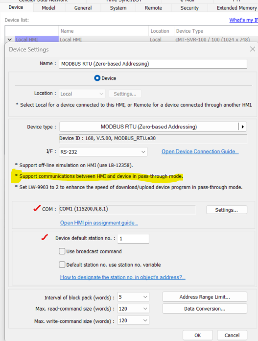
UPDATE: “Device No Response”. Please let me provide more detail. Using a cMT-SVR-100 reading Modbus RTU data on Com1 pins 2 & 3. Writing Modbus TCP/IP out LAN1. So, created Device 1 - MODBUS RTU (Zero based Addressing) and Server Device MODBUS SERVER. The screen I created represents light for several of the 1X bits and display values for 3X registers. Question…if I don’t also include the device MODBUS TCP/IP (Zero based Addr) how can I show these values on my screen? I created a similar project years ago except LAN1 output to DEVICE=Rockwell Ethernet IP. I used GET / SET Macro and all worked well. Now I keep getting the same error…“Device No Response”. Does this mean the device on COM1 or LAN1? LAN1 will be a network SCADA which is currently not connected because I am testing in the office, but COM1 device is connected. Currently, I can’t determine how to confirm MODBUS RTU comms on COM1 are active…any suggestion? So far, I basically stripped out everything and just trying to READ MODBUS RTU bits but still no luck. Can I send you the program for your review? Thanks
I am reading Modbus RTU values from a Sulzer PC 441. Default Com Port values: 115,200 Baud, Parity: none, Handshake: off, Protocol ID: 1, Message Timeout: 2sec.
An easy way to check connectivity, is to see if an object addressed to the Modbus RTU device will display. To do this, we recommend that you place a single object, like a bit lamp on the visible area of your project and download it to your device. Then, check if the HMI renders this object. If the object is not displayed, this indicates that the HMI was unable to poll a value for this object / address.
Also, I was not able to find the Modbus mapping manual for this controller. However, some other manuals seem to indicate that this device may use 1-base addressing. In this case, please use the “Modbus RTU, RTU over TCP” driver instead.
Note: A device using a 1-base addressing will begin with an address of 1 instead of 0. This is the most common address offset for Modbus devices.
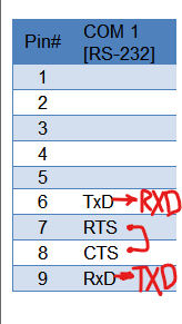
Yes, I have tried a single bit and Modbus RTU, RTU over TCP and used the same Comp 1 comms wiring RXD-TXD, TXD-RXD. I originally completed a similar project (same Sulzer PC441) sometime ago where I used the Modbus RTU/zero based addressing driver to read the Sulzer values. I then used the Get/Set commands to output data to an AB Ethernet IP MicroLogix out LAN1. I have the Modbus manual for the Sulzer. I have seemed to try everything even a second cMT-SVR-100. Now I am going to try and HMI and read from the Com Port. Don’t know what else to try after. Thanks
Just to confirm, did the bit lamp in your test described above display? Also, do you have a USB to RS-232 cable you can use to test a 3rd party Modbus client application in order to rule out any differences in the Sulzer PC441 device?
No, it does not display. The Com Port of the Sulzer that states Modbus RTU default capability has terminal blocks so that is why I am using flying leads from the terminal block to the Weintek Com 1. RXD-TXD, TXD-RXD and gnd. Again, I have done this before and using all the same equipment and schematic but no luck.
Reading your previous note…you have a 3rd party application that you would like me to try? If so, I do know the pinouts of all the terminal blocks of the Sulzer Com Port.
I also have a small non CMT HMI that I am experimenting with now trying to Read Modbus via COM1…but no luck.
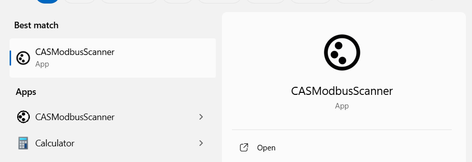
There are a few 3rd party applications that I use when troubleshooting, but I use the CAS Modbus scanner most often. They have a feature in their software that allows connections to Modbus TCP and Modbus RTU devices.
I just received my USB - RS232 troubleshooting cable and using CAS MODBUS Scanner I am able to read Modbus Data bit data from the Sulzer. What would you recommend for trouble shooting the cMT-SVR program Com 1? Something simple like trying to read a Bit, but what driver would you recommend? I tried Modbus RTU zero base Modbus RTU RTU over TCP but no luck. I validated comms settings…I just don’t know what to try next. Thanks.
Thank you for confirming, can you please follow the instructions within this post to check if you can read data from these devices using online simulation within EasyBuilder Pro?
Thank you for the update, and that’s exactly what I was going to suggest! If the register data works, I would suggest that we download the application that works in online simulation to the HMI next and test that. If possible, I would recommend using a different serial cable to connect the HMI and PLC in the following test just to verify that it isn’t a faulty cable.
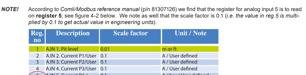
I added analog inputs to the Sulzer and corresponding register values to the program, but I did use the same hardwired cable (w/flying leads) because it was already attached to my USB -RS232 breakout connector used previously and all is working! So do I now try to load this example program into the cMT-SVR but change the Device driver to Com1 of the cMT-SVR? Thanks
Yes, now you can load this application into your HMI for testing. And, as mentioned if possible please switch the serial cable if the connection does not initially work. Thank you for the update!
I noticed that all the bits and registers are off by one, so I replaced the driver with Modbus RTU Zero Based Addressing and changed the Com port to 1. Downloaded the program and I can read values in both Online Simulation Mode and via the cMT Viewer. However, once I disable either communication, I notice the communication with the Sulzer controller also stops…no RXD or TXD light flashing on face of Sulzer controller. Typically, the next step would be for the cMT to send Com 1 Modbus RTU data out LAN1 TCP/IP to the SCADA which will only be reading data and acts as a Client. How do I keep cycling the cMT Comm 1 to Read data from the Sulzer? Will the above-mentioned video from May 22 comments (Modbus Server) create that action from the Modbus table? Thanks
UPDATE: I added the Modbus Server (added LAN1 IP) and created mapping tables (not sure if I was suppose to select “use UDP” will verify later). Downloaded and noticed I get an error in Online simulation Mode, but everything works when cMT Viewer is active. Once I disable cMT Viewer communications with Sulzer stops.
UPDATE: To keep the cMT communicating in the background I created a repeating Macro for Modbus RTU driver to Get some bit data…will this accomplish what I need to keep the cMT Com 1 to continuously reading data? Since I had previously created Modbus mapping I connected to Lan 1 using CAS Modbus to see if I would be able to Read Modbus TCP data but “could not connect”. I assume my config is wrong somewhere. How does the Modbus Server know to Write (or Read data available) at Lan1?
UPDATE: Using CAS Modbus the TCP connection Config…IP address must equal the LAN1 and the port # must equal the IP Port setting in the Modbus Server device. I assume the SCADA reading of LAN 1 activated the reading of all Modbus RTU data of Com1? Thanks
To better assist with this issue, can you please send the HMI project and the serial number of the HMI to support@weintekusa.com. This will allow us to review the current setup to see if there is any explanation for the behavior shown below:
Also, just to clarify, is the end goal of the application to allow SCADA to read to the Modbus RTU devices?