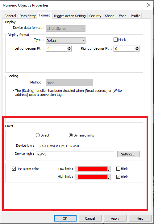
Hi my question is regarding the limits for the numeric object, I have them set to blink in red if they reach certain value.
Let say the numeric object value reached 20 being one of the limits, the numeric object doesn’t blink until it reaches above 20.
My question is the logic for this limit alarm to activate is
limit value < Numeric Object value
And can it be changed to
Limit value <=Numeric Object Value
Currently the limit logic cannot be changed, but a simple solution may be to make your high limit equivalent to 1 less than the actual high limit and your low limit to 1 more than the desired low limit. In your example, you should set the high limit to 19 instead of 20 to have it blink when the value is 20 or above. Will this solution work within your application?
Brendon,
That would work if I had static limits I have dynamic, it is not a big deal I was just curious if there was a way to modify the limit logic.
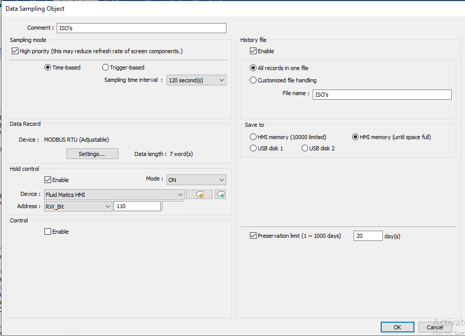
All though I do have a question regarding data sampling I was able to get email trends or extract them via usb in the same program but I tried to today and no trending data file is being created any ideas ?
Regarding the data sampling inquiry, as long as the hold control address was FALSE and the HMI was allowed to run at least one sampling interval, 120s in this case, a backup should have triggered an export. Can you please test this one more time and place a “Historical Data Display” object within your project to verify that at least one row of data exists prior to backup?
So I left the unit with the program running all night to see if it would create data, I proved the hold control bit is going on and off when it is supposed to with a bit lamp.
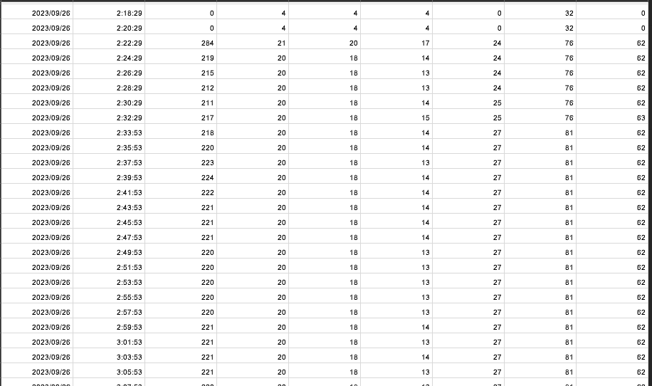
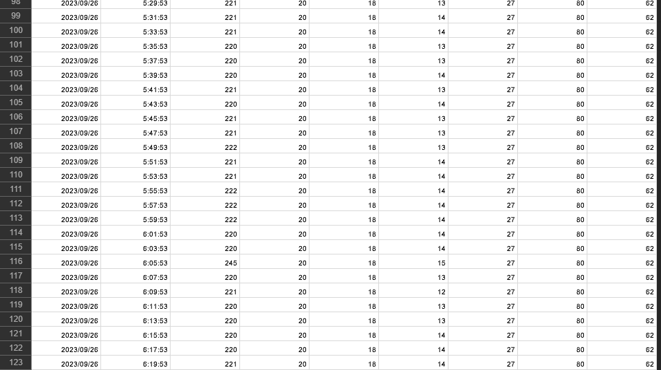
weird thing it started recording today around 2 am
then it stopped recording around 6 am when the unit is still running any ideas?
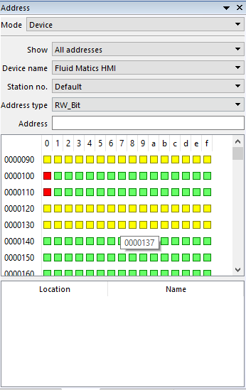
Without seeing your project I cannot determine what triggered the hold address at 2:00 AM. I highly recommend that you use the Find & Replace tool or the address grid to determine what objects or macros write to RW_Bit-110 or RW-11. After you investigate this issue, please let me know the result. Thanks!
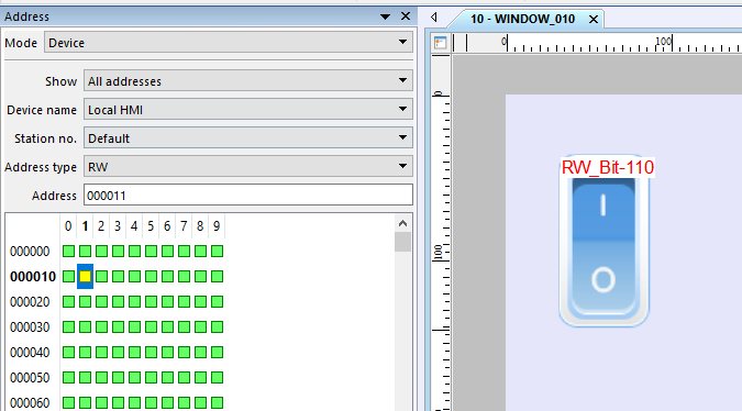
I discuss yellow blocks at 2:14 within the address grid tutorial. But in summary, a yellow block may indicate that a specific bit is referenced by a word object or that a word is referenced by a bit object. As an example, if I assign a toggle switch to RW_Bit-110 then RW-11 will be yellow within the address grid unless I have another object that references the entire RW-11 word:
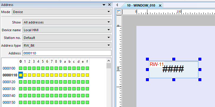
Similarly, if I have a numeric object that references RW-11 then RW_Bit-110 ~ RW_Bit-11F will display as yellow unless I reference a specific bit within a bit object or macro: