- HMI Model: MT8072ip
- EasyBuilder Pro Version: V6.10.02.394
Hello,
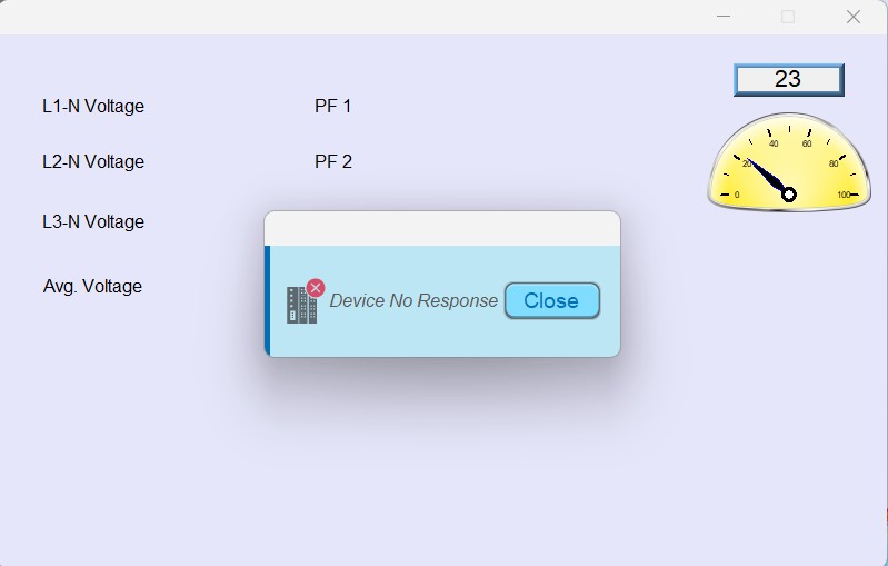
I am trying to communicate with an energy analyzer from Acuvim L via RS485 COM2 on the HMI. I tried every possible connection, wire swapping, and register address, but I am still getting the “Device No Response” message. I checked the Acuvim L meter via ModScan, and I am getting voltage and frequency values.
I still don’t understand how a simple connection is becoming a problem.
The 9-pin DB9 connection is from Acuvim RS485 A → HMI Pin 1 and RS485 B → HMI Pin 2.
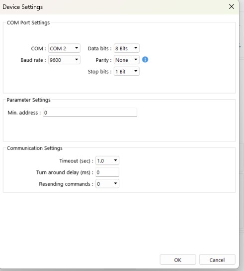
The baud rate, parity, and stop bits match the same on both devices.
Can anyone guide me on where I am missing something, or is there any register on the HMI to check whether communication is established with the device?
Hi @mohsin160 ,
Thank you for your question. What driver are you using in the project?
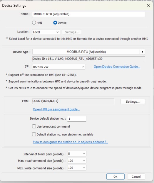
Additionally, could you provide screenshots of your Modbus configuration in the driver settings? This will help us better understand your setup and troubleshoot the issue.
I am using MODBUS RTU (Adjustable), but I tried MODBUS RTU (Zero-Based Addressing) and MODBUS RTU, RTU over TCP as well, but nothing removes the Device No Response Error for me.
The screenshot is attached.
Hi @mohsin160 ,
Thank you for the additional information.
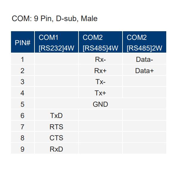
To continue troubleshooting, can you please confirm that the RS485 wiring matches the pin assignment for the MT8072iP? Here is the pin assignment guide for your reference: HMI Pin Assignment Guide.
We also recommend using the Modbus RTU, RTU over TCP driver in EasyBuilder Pro, if possible.
I have tried the Modbus RTU, RTU over TCP as well with the pin out as described in the document but i still cannot get the device working. The error of Device no response is still there.
RS485 A data from the Acuvim goes to HMI pin 2 and RS485 B data goes to pin 1 on the HMI.
Hi @mohsin160 ,
When you have the chance, could you run an online simulation from your PC, following the steps outlined in the forum post below?
How to use “Online Simulation” with a serial device
Please let us know if you encounter any error messages while running the simulation.
Additionally, could you please clarify whether you are able to read any data from the HMI? This will help us better understand the issue and determine the next steps for troubleshooting.
Thank you!
Hello Arden,
I have checked the Online Simulation with a serial device (RS485-to-USB converter). I am getting the data from the energy meter via ModScan as well as in the Online simulation in EBPro.
The serial device was COM7 on the PC and the parameters set were No Parity, 8 Stop Bits and 9600 Baud Rate.
Hi @mohsin160,
Since communication works within an online simulation this indicates that the project parameters and driver selection are correct and that the address types used to read the device data reference the correct Modbus function codes. In this case, we would recommend that you double check the pinout connections of the cable used to connect your HMI to this device and verify continuity using a multi-meter.
Hello Brendon,
Noted. I will check the cable and pinout. Just for reference can you please guide on what will be the voltage between Pin 1 and Pin 2 of the DB9 connector?
Hi @mohsin160 ,
The voltage should be roughly 3.4 V. For reference, the pinout guide is provided below to check the cable’s continuity and verify the connections.
Hello Arden,
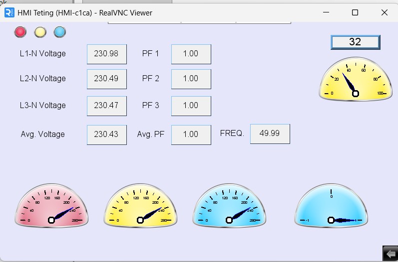
Thanks a lot for the reply and the guidance on the issue. Now I have the data from the energy analyzer and have displayed it on the HMI.
The problem now is that if I change some addresses on the EBPro, I cannot get the Online Simulation working (It gives a Device No Response error), whereas to view the changes made, I have to transfer the program to the HMI to check the functionality of the changes made from the HMI screen.
I need to know why the Online Simulation feature is not working for me.
Screenshots are attached for reference.
Hi @mohsin160 ,
Thank you for the screenshots and the additional information. Online simulation runs the HMI project on the PC and requires the PC to communicate directly with the PLC, while VNC Viewer simply mirrors the actual HMI screen, with the physical HMI continuing to communicate with the PLC.
Based on the screenshots, the HMI-to-device communication appears to be working correctly, as the VNC application is displaying the device data.
To help ensure the online simulation is working properly, please also verify that the COM port configured on the PC matches the virtual COM port selected in the HMI IDE, as outlined in the post referenced above.
Hello Arden,
Now as I am getting the HMI working with Acuvim meter connected with the HMI via RS 485. The HMI is connected with the network switch via CAT6 cable and my laptop is also connected with the same network switch. In this scheme I can upload the program to the HMI.
With this connection scheme how can I remove the Device No Response at the Online Simulation because I am not using the RS485 to USB adapter?
Regards
Hi @mohsin160,
The online simulation feature allows your PC to emulate an HMI in order to test the project before downloading it to a device. When using this option you need to have a physical connection between your PC and PLC. If you do not have a USB - RS485 cable or other connection to your PLC, this method will not work.
If you want to simply monitor what the HMI is displaying from your PC, you can use a VNC client application instead as in this tutorial.