Introduction:
In this post, we describe how to display data sourced from a PLC or other device within an alarm message. This process involves mapping a device value to what we call a ‘WATCH’ address within an alarm and then referencing it using a special syntax.
Software Version:
EasyBuilder Pro 6.03.02.463+
Instructions:
-
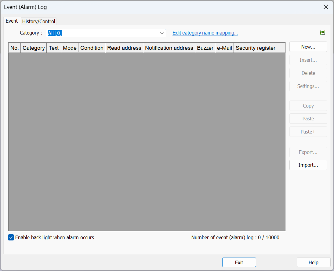
Within the “Data/History” tab, open the “Event (Alarm) Log”:
-
Select “New…” to create a new alarm or open an existing alarm:
-
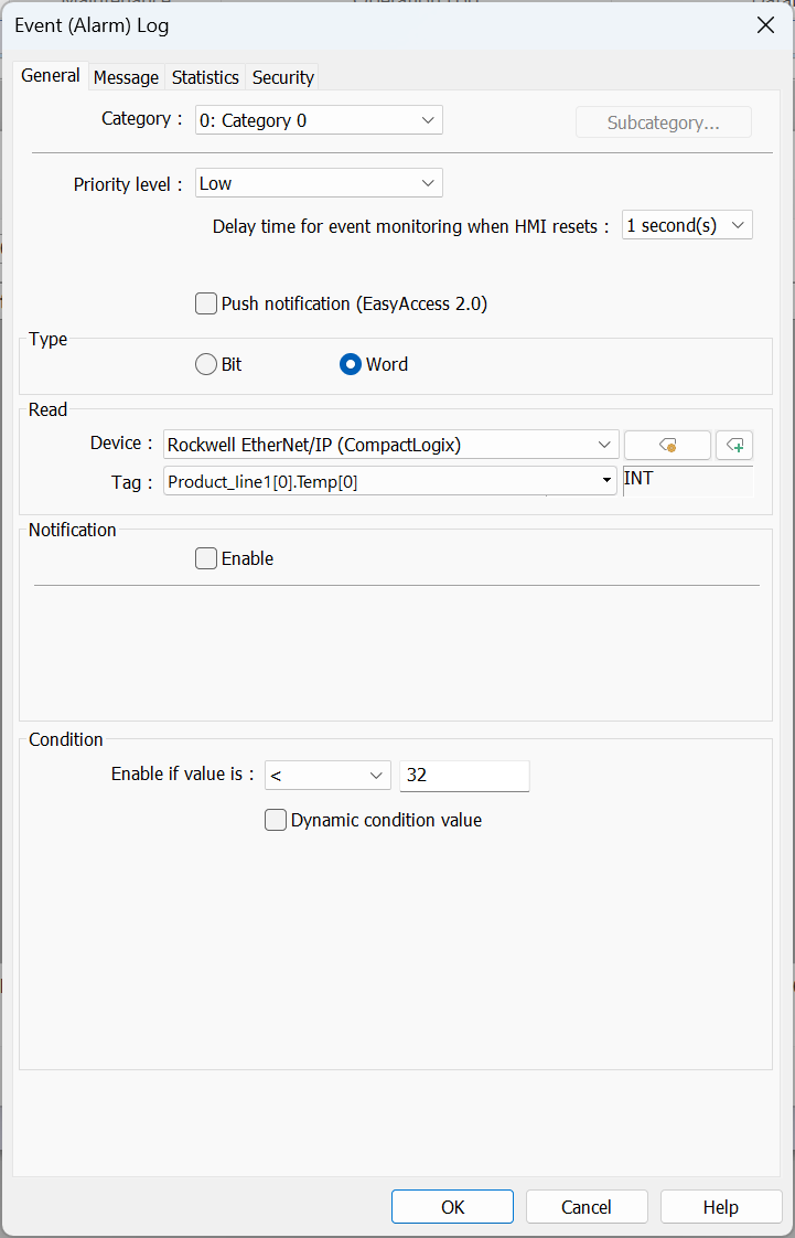
Configure the alarm settings as needed:
-
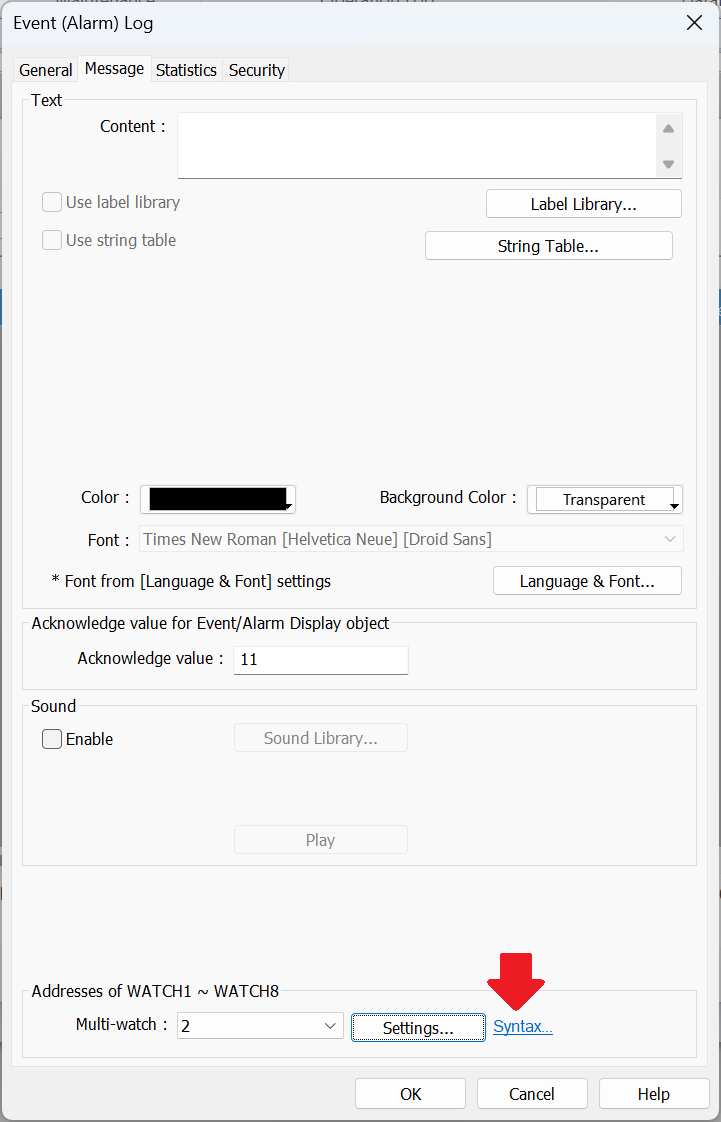
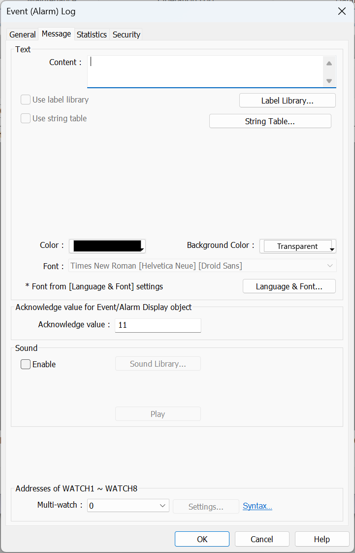
Select the “Message” tab to design the alarm message:
-
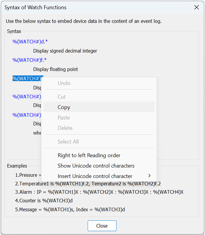
To display a value within the PLC, we will use the “Multi-watch” feature with the following syntax:

| Syntax | Description |
|---|---|
| %(WATCH#)d.* | Display signed decimal integer |
| %(WATCH#)f.* | Display floating point |
| %(WATCH#)s | Display string |
| %(WATCH#)X | Display unsigned hexadecimal integer, using “ABCDEF” |
| %(WATCH#)x | Display unsigned hexadecimal integer, using “abcdef” |
| Character(s) | Description |
|---|---|
| # | ‘#’ should be replaced with the number of the watch address, possible values are 1 ~ 8. |
| .* | ‘.*’ should be replaced with the number of digits after the decimal point, but may be removed if that number is 0. |
-
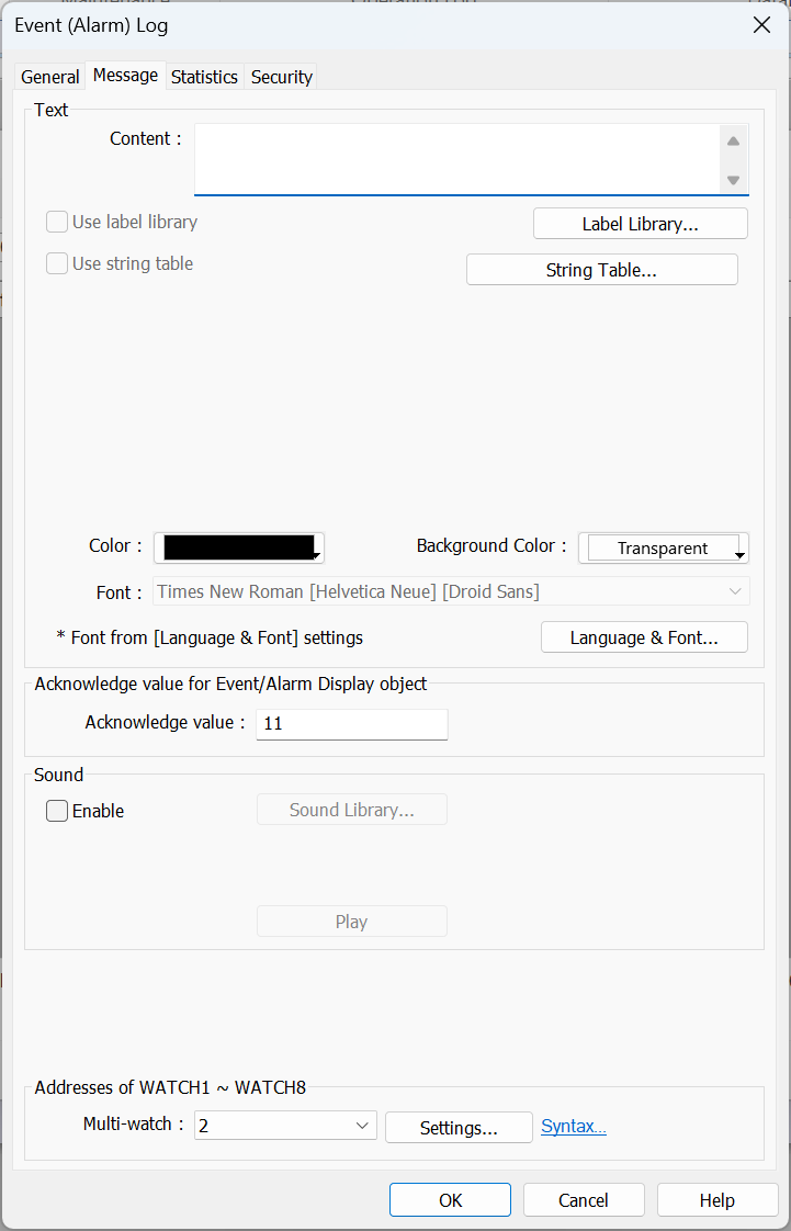
The watch syntax is mapped to a watch address via the “Multi-watch” drop-down list and “Settings…” button:
-
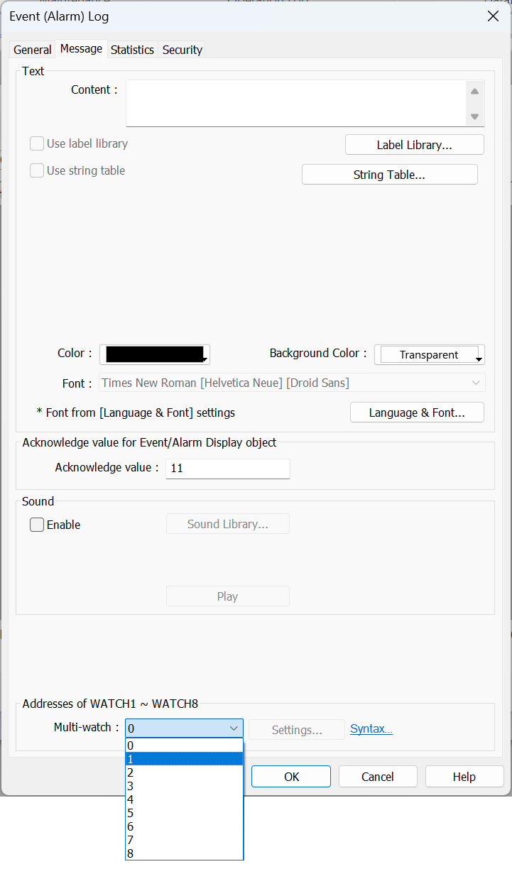
To add a watch address, set the “Multi-watch” drop down list to an a number greater than 0:
-
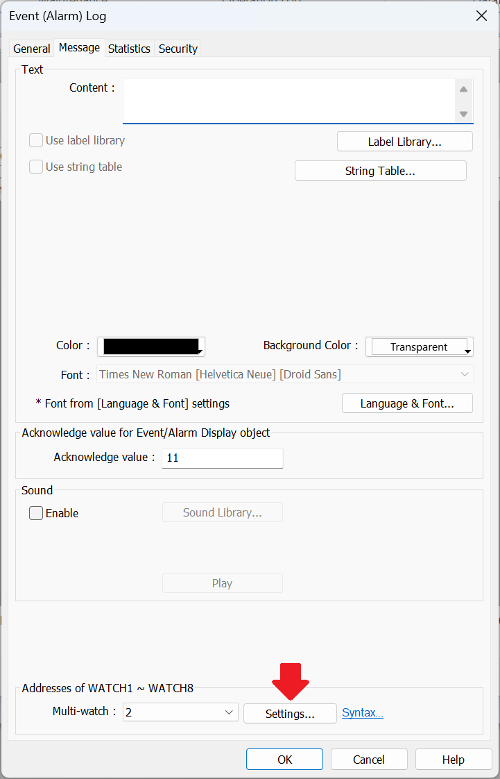
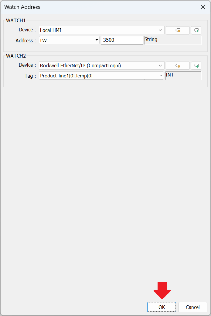
Select the “Settings…” button to configure the watch address mapping:
-
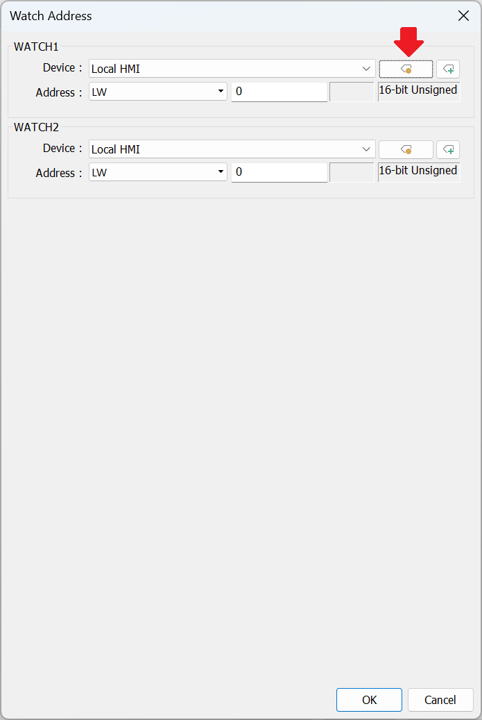
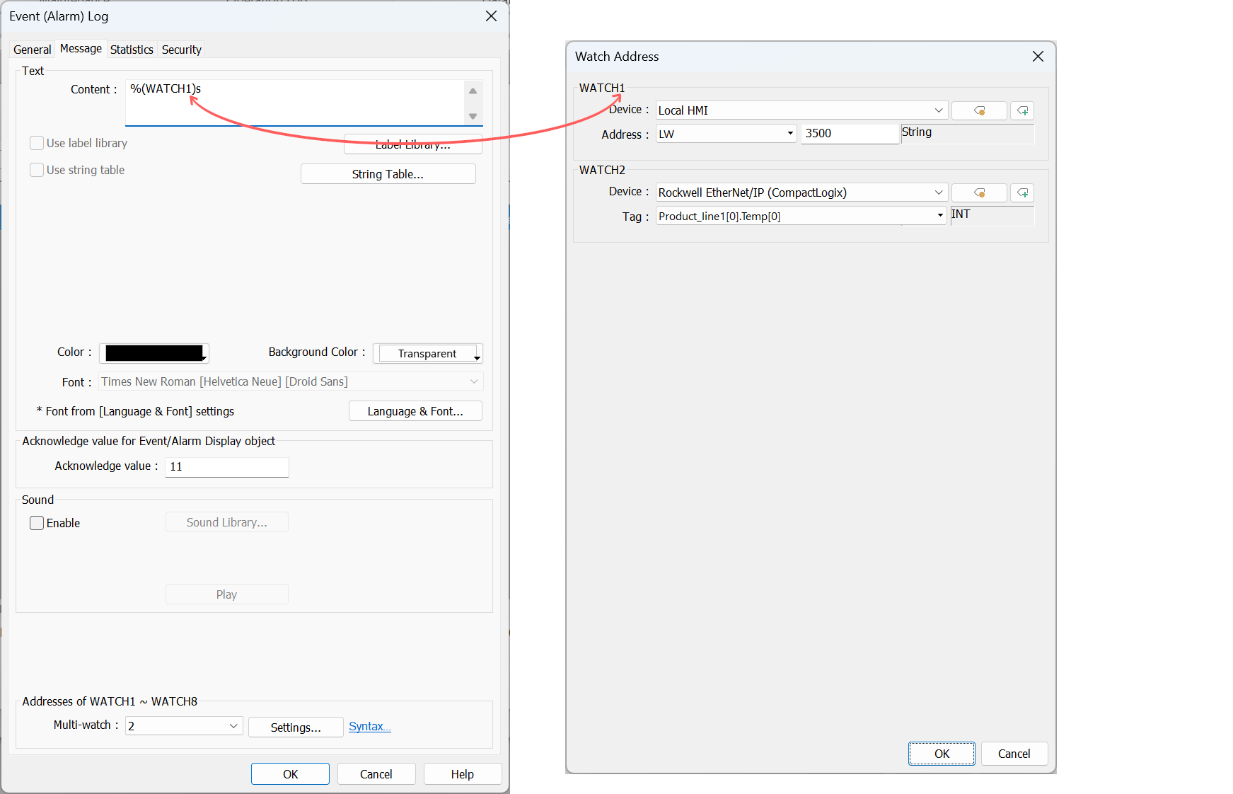
Select the WATCH1 “Settings…” button to select the data type and data source:
-
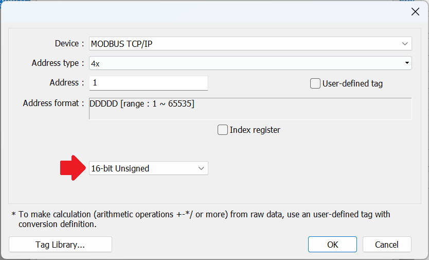
Since the data source selection and menu options may change depending on the device type used, we have provided a few examples below for reference:
Note: In this example, the data type of the register-based data source has been set to “16-bit Unsigned” using the type drop-down list.
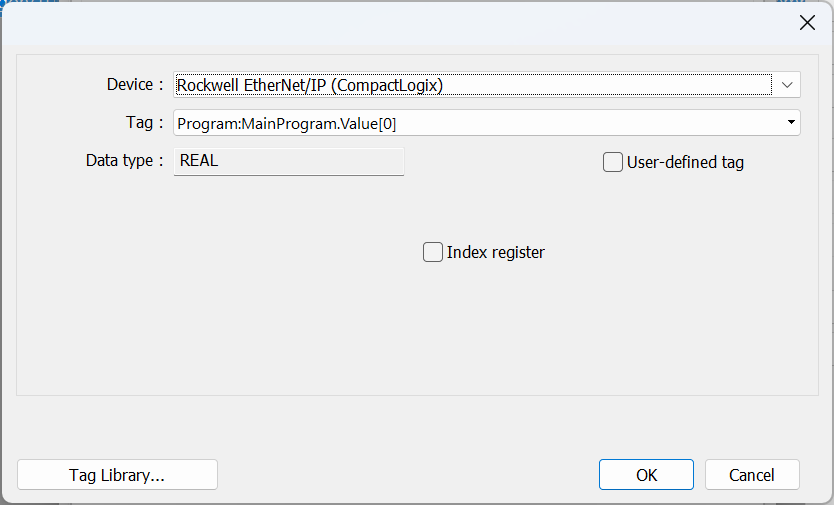
Note: In this example, the data type of the tag-based data source was automatically set based on the data type of the tag.
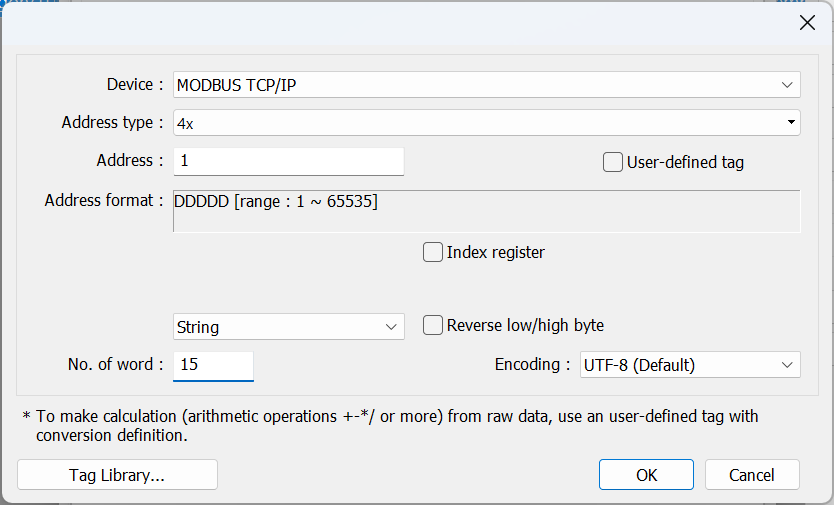
Note: In this example, the data type of the register-based data source has been set to “String” using the type drop-down list. The String length has been set within the “No. of word” input field. The “Encoding” method should be set to match the device’s preferences. However, most devices use either UTF-8 or Unicode with the former providing 2 characters for each “word”.
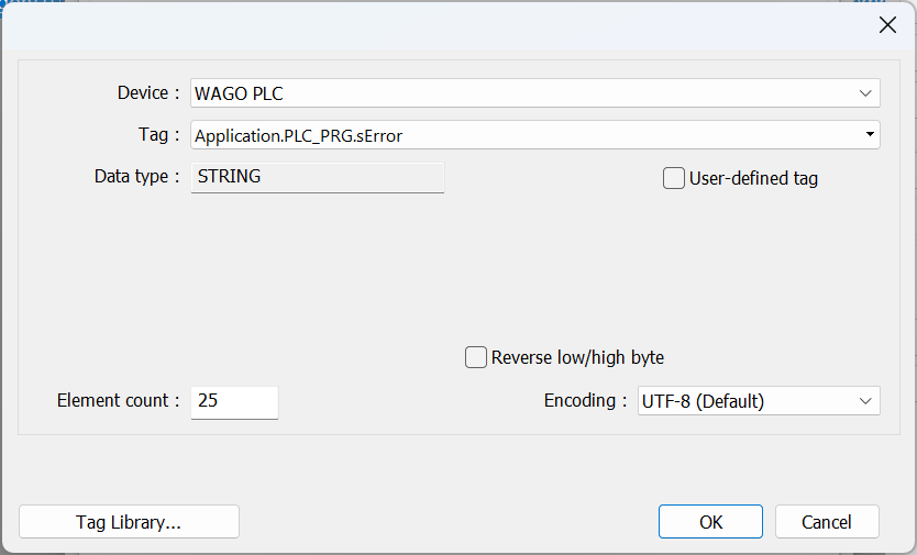
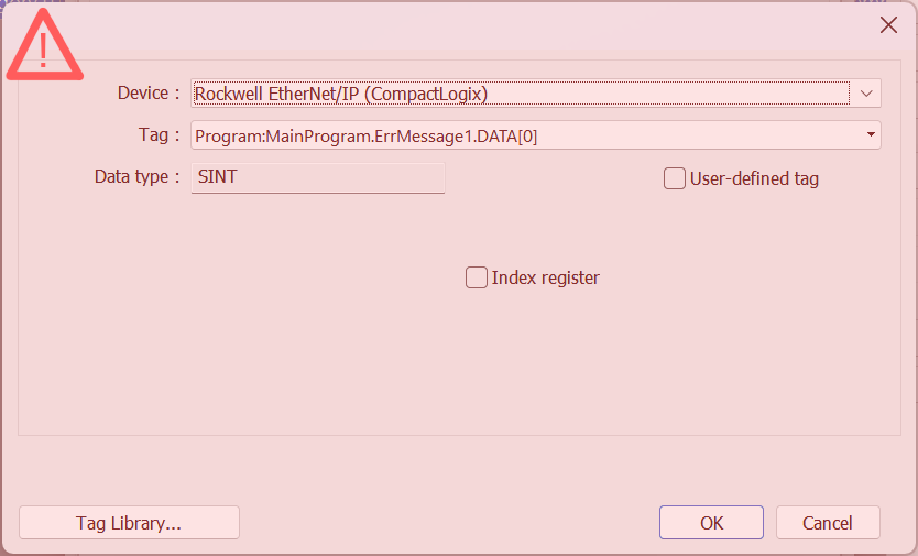
Note: In this example, the data type of the tag-based data source was automatically set to “STRING” based on the data type of the tag. The “Element count” may be used to adjust the number of displayed characters, while the “Encoding” method should be set to match the device’s preferences.
Note: Some tag-based PLCs, may store string data within an array such as in the case of the CompactLogix. In this case, it is not possible to map the string value directly. Therefore, to display the STRING value within an alarm, we will need to transfer the string to HMI memory and then map the watch value to the transfer destination.
-
After setting the WATCH address and data type, click “Ok” to close the “Settings…” menu:
-
Select the “Syntax…” option to copy the appropriate WATCH syntax:
Note: See syntax options in step 5.
-
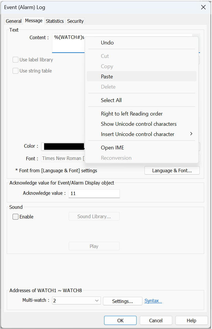
Copy the syntax:
-
Paste the syntax into the “Message” input field:
-
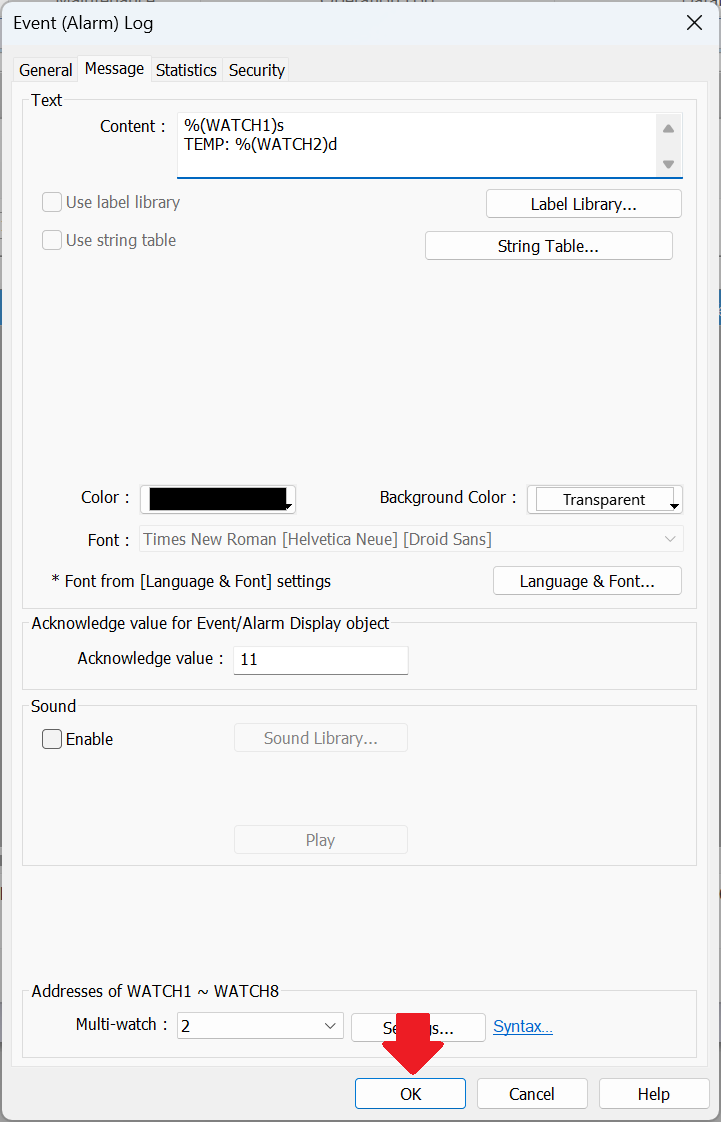
Modify the syntax to add set the appropriate watch numbers:
-
Click “Ok” when finished to set your alarm:
-
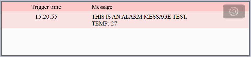
Simulate or download the application to test the alarm message output: