Introduction:
EasyBuilder Pro provides several methods that can be used to transfer data to a device, even if the data to be transferred was polled using a different protocol. Within this post, we outline the procedures used to transfer data.
Software Version:
EasyBuilder Pro 6.03.02.393+
Instructions:
Macro:
Typically, we recommend using a Macro to transfer data. The process of configuring several data transfers within a Macro can be much faster than when configuring those within a “Data Transfer (Global)” object. Using a Macro also provides the opportunity to manipulate data before it is sent to the receiving device. Within this section we describe how to use a Macro to transfer data.
-
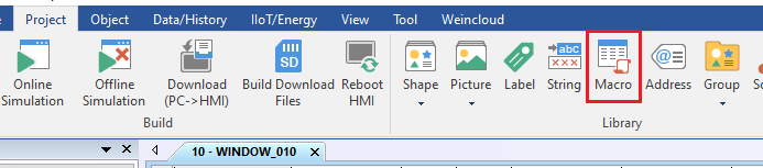
Within the “Project” tab click “Macro”:
-
Within the following menu, click “New”:
-
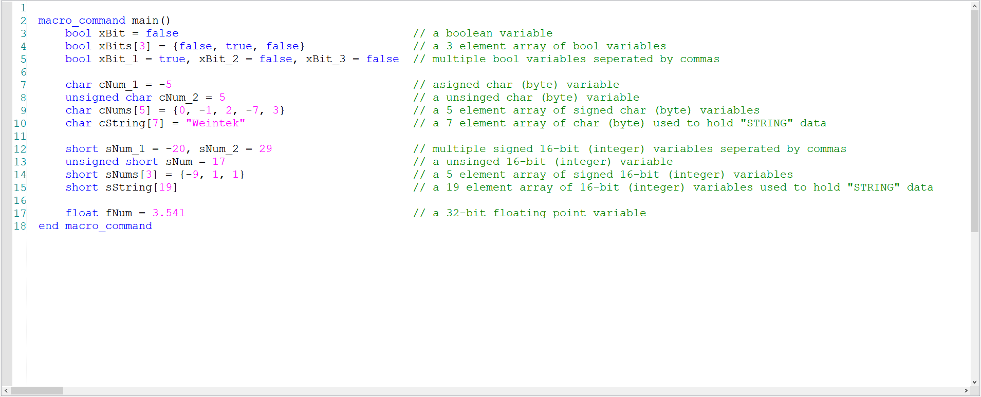
The Macro workspace supports the following data types:

| Declaration | Type | Equivalent | Range | |
|---|---|---|---|---|
| bool | bit | BOOLEAN | 0 ~ 1 | |
| char | byte (signed) | SINT | -128 ~ 127 | Note 2 |
| short | 16-bit (signed) | INT/WORD | -32768 ~ 32767 | Note 2 |
| int | 32-bit (signed) | DINT/DWORD | -2147483648 ~ 2147483647 | |
| float | 32-bit (float) | REAL | ||
| unsigned char | byte (unsigned) | USINT | 0 ~ 255 | |
| unsigned short | 16-bit (unsigned) | UINT | 0 ~ 65535 | |
| unsigned int | UDINT | 0 ~ 4,294,967,295 | ||
| long | LINT | -248 ~ 248 | Note 1 | |
| unsigned long | ULINT | 0 ~ 248 | Note 1 | |
| double | LREAL | -248 ~ 248 | Note 1 |
Note 1: See appendix D [Link] for information related to the limitations of 64-bit support.
Note 2: A char array is used to represent STRING data in register-based PLCs. A short array is used o represent STRING data in certain tag-based PLCs.
-
To transfer data, a variable large enough to accommodate the data that will be transferred must be declared. To declare a variable, please use the following format: [Declaration] [Name]. Here are some examples:
-
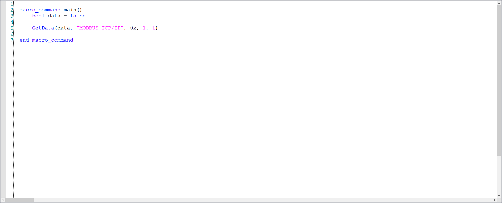
To read data from a device, move your cursor to a blank line and select the “GET/SET FN…” button in the bottom left corner:
-
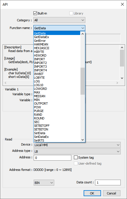
Within the following menu, select “GetData” from the “Function name” drop-down list:
-
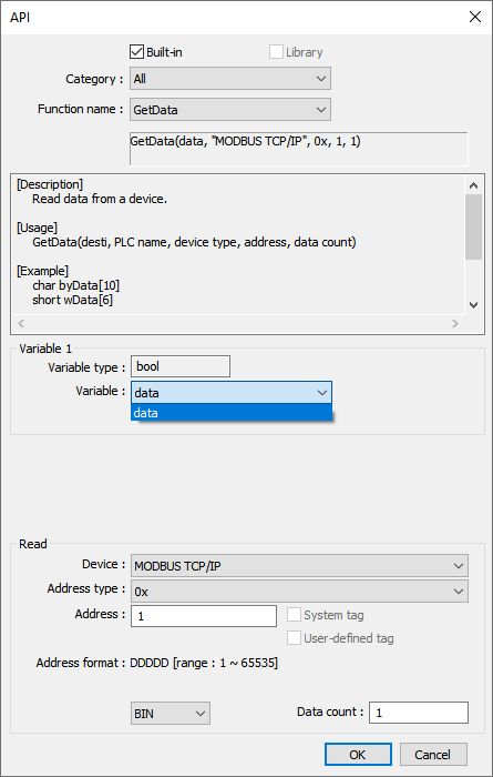
Select the appropriate variable from the “Variable” drop-down list:
-
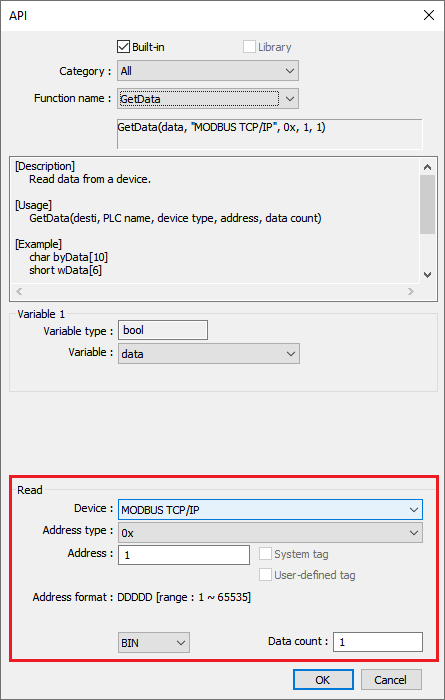
Define the “Read” address and “Data count”:
Note: The data count may be used if you are retrieving data from more than one address with the purpose of filling an array.
-
Click “Ok” when finished:
-
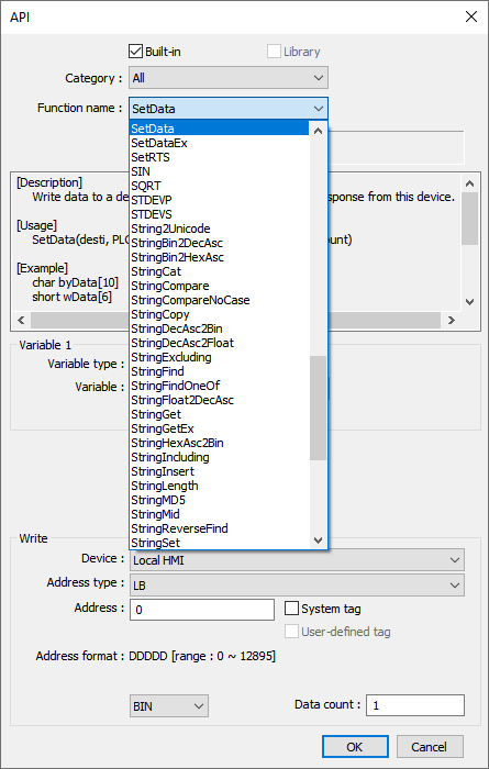
To write data to a device, move your cursor to a blank line and select the “GET/SET FN…” button in the bottom left corner. Within the following menu, select “SetData” from the “Function name” drop-down list:
-
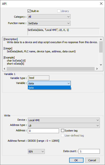
Select the variable that contains the data that you would like to write from the “Variable” drop-down list:
-
Define the “Write” address and “Data count”:
-
Click “Ok” when finished:
-
To transfer an array of data simply ensure that the “Data count” is set accordingly:
Note: The data count is specified at the end of the string.
-
To add other transfers within the same macro, define additional variables or arrays as needed, and then copy and paste the “GetData” and “SetData” statements:
-
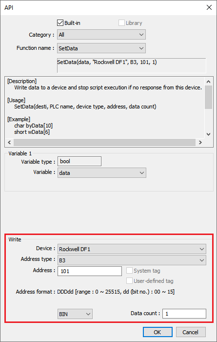
Each parameter including the “Address type” (red) and “Address” (orange) can be modified directly, their is no need to utilize the API assistant when creating each “GetData” and “SetData” statement:


Examples:
-
7 characters of STRING data are read from the Compact Logix into a variable called “data” The value of this variable is then written into Modbus register 4x-10:
-
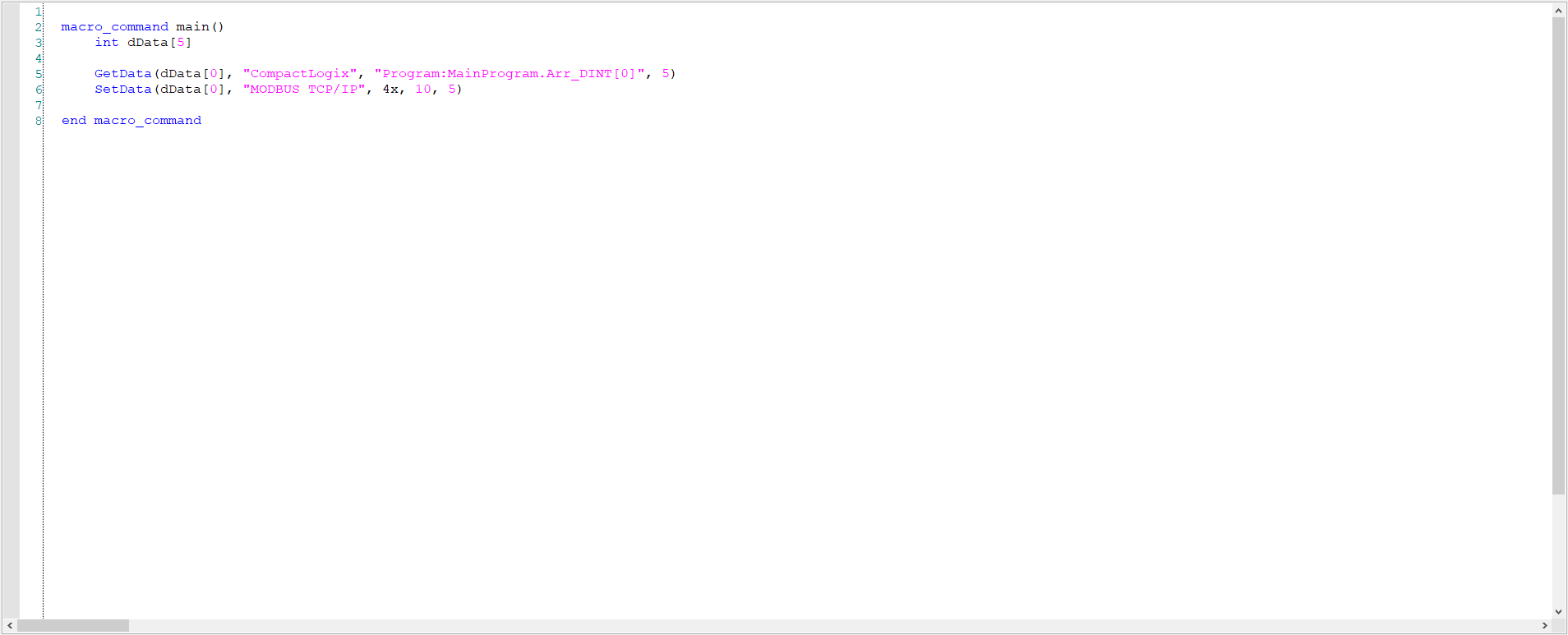
An array of 5 DINT values are read from the Compact Logix into a variable called “dData”. The value of this variable is then written into Modbus register 4x-10:

Data Transfer:
The “Data Transfer” object may be used to transfer word data between various devices within your project. However, current limitations prevent it from writing boolean data to certain external devices. Therefore, if your your application requires you to transfer boolean data, please consider using a Macro to perform data transfer instead. Within this section we describe how to use a “Data Transfer (Global)” object to transfer data.
-
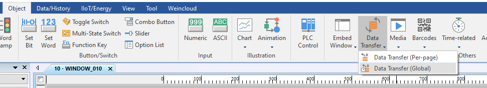
Within the “Object” tab, select the “Data Transfer” drop-down list and click “Data Transfer (Global)”:
-
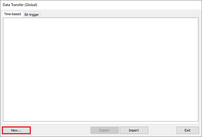
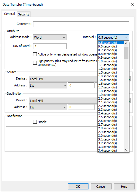
Within the following menu, click “New” within the “Time-based” tab:
-
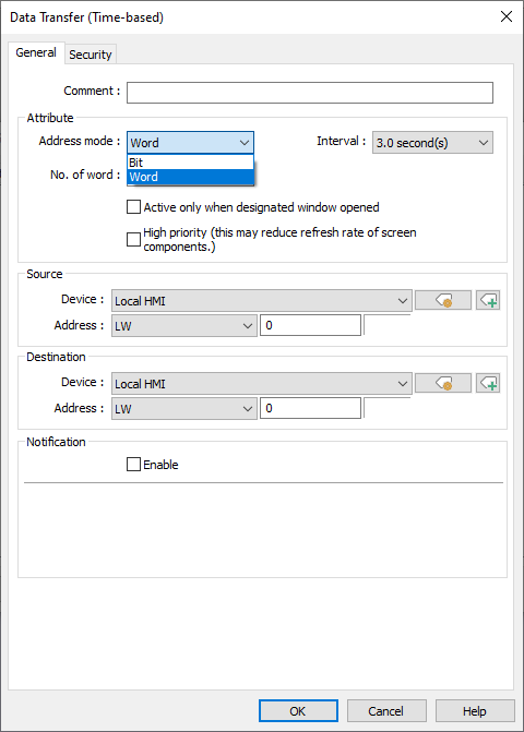
Within the “Address mode” drop down list specify the type of data to transfer:
-
Ensure that the “Interval” is set to an appropriate value and note that while the HMI will attempt to perform the transfer within the specified interval, the time required to transfer data depends on certain external factors such as system load and the communication rate between the HMI, source device, and destination device:
-
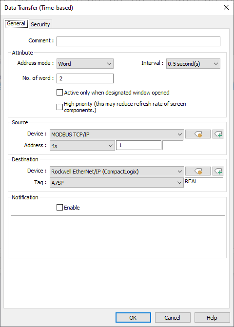
Configure the “No. of word” and note that this value should be equivalent to the number of words, bits, or tags that will be used. The label “word” will change according to the type of data that will be transferred and the architecture of the source device. Specify the source address of the desired data and the intended destination:
Note: To transfer data that contains a floating point the appropriate “No. of word” must be configured.
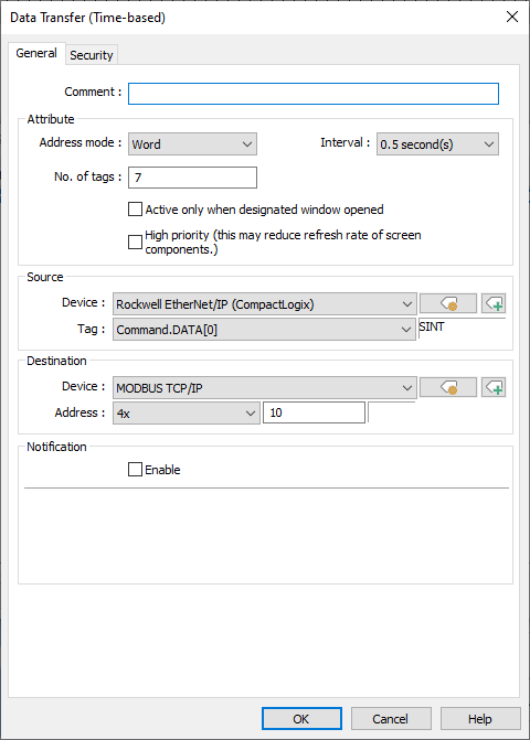
Examples:
-
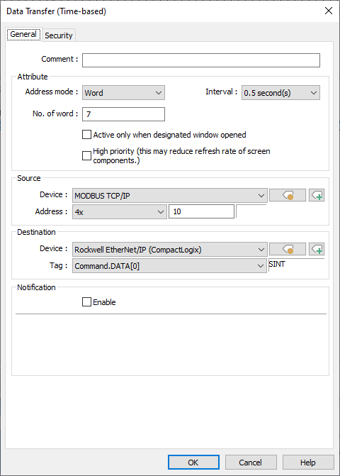
To transfer a STRING, ensure that the correct “No. of word” is set. However, due to different encoding methods the STRING data may not transfer in its intended form. If it seems that every-other-letter is lost or a space is added between every-other-letter, please use a Macro to transfer data instead:
Note: This transfer may result in a space being added between characters.
Note: This transfer may result in every other letter being removed.
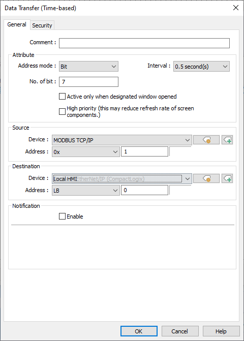
-
EasyBuilder Pro may reject certain devices from being used as the “Destination” address while the “Address mode” is set to bit. If this occurs, please use a Macro to transfer data instead:
Note: The “Rockwell Ethernet/IP (CompactLogix)” device was selected within the “Destination” address, but it quickly fades away due to limitations related to boolean support. Therefore, a Macro must be used instead.