Introduction:
This post contains step-by-step instructions that explain how to import an iR-ETN’s EDS file into Logix Designer and interpret IO mapping.
Software Version:
Logix Designer 33.00.00+
EasyRemote IO 1.4.7.0+
Instructions:
While using Logix Designer 33.00.00+, utilize the following method to import the iR-ETN’s EDS file:
-
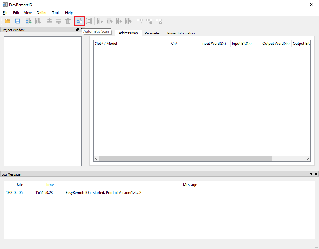
Within “EasyRemoteIO”, select “Automatic Scan” to find the iR-ETN and connected IO:
-
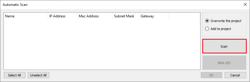
Select the “Scan” button to scan for connected IO:
Note: If the iR-ETN is not found, please follow the instructions within this post to add the iR-ETN.
-
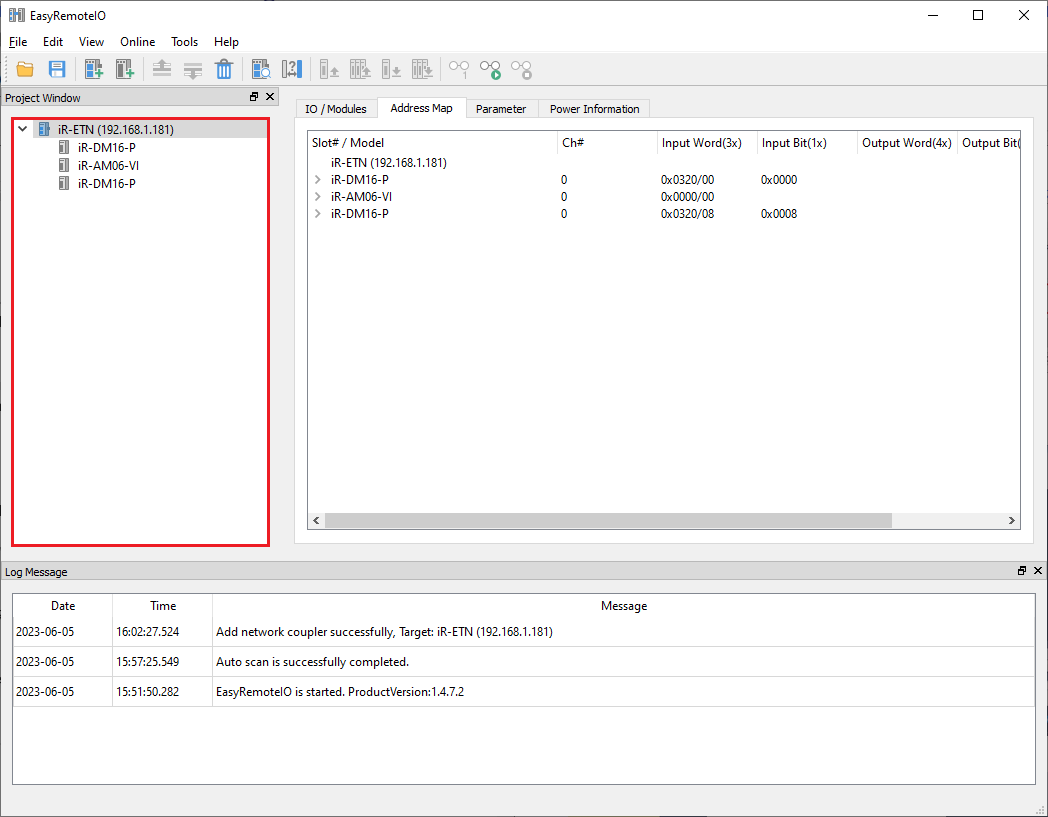
Once found, click “Ok” to add the iR-ETN to the project window:
-
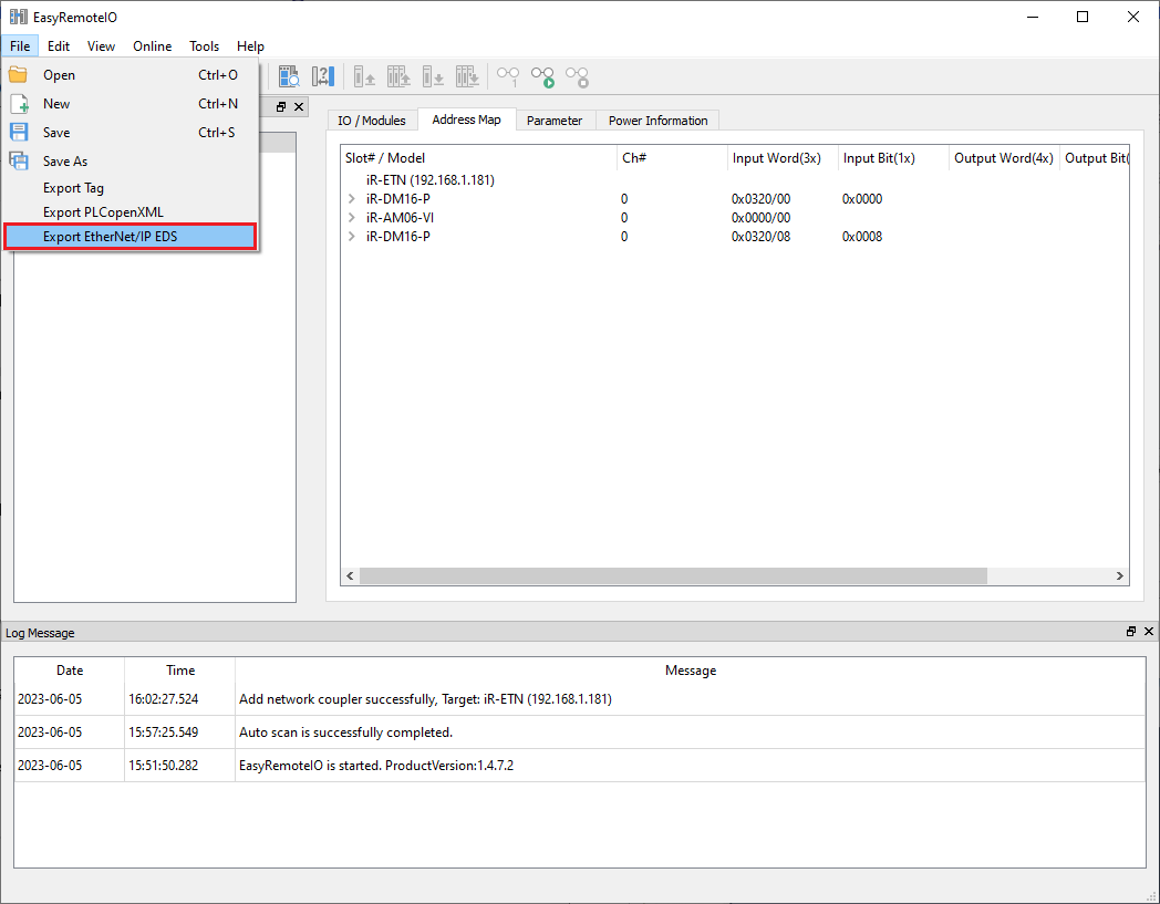
Within the “File” tab, select “Export EtherNet/IP EDS” and determine a directory in which the EDS file should be saved:
-
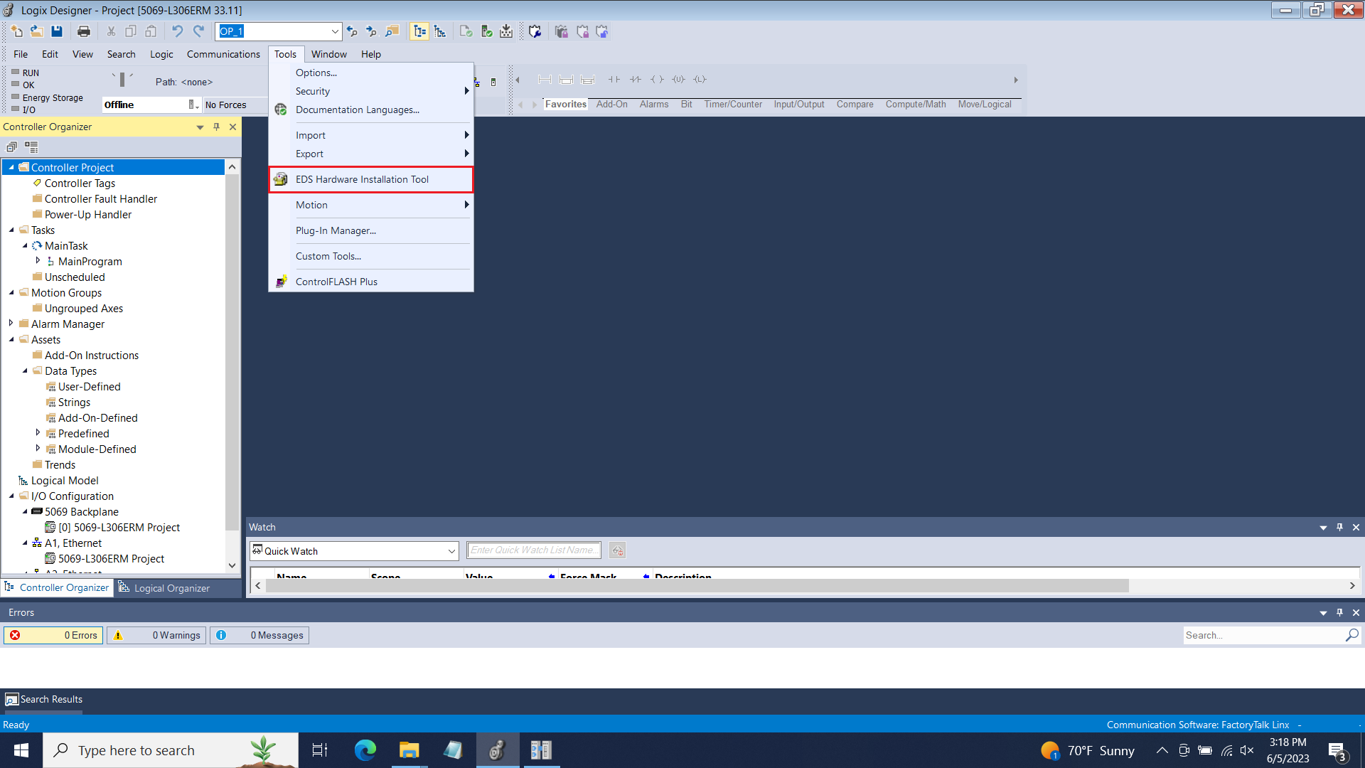
When finished, select “EDS Hardware Installation Tool” within the “Tool” tab of Logix Designer:
-
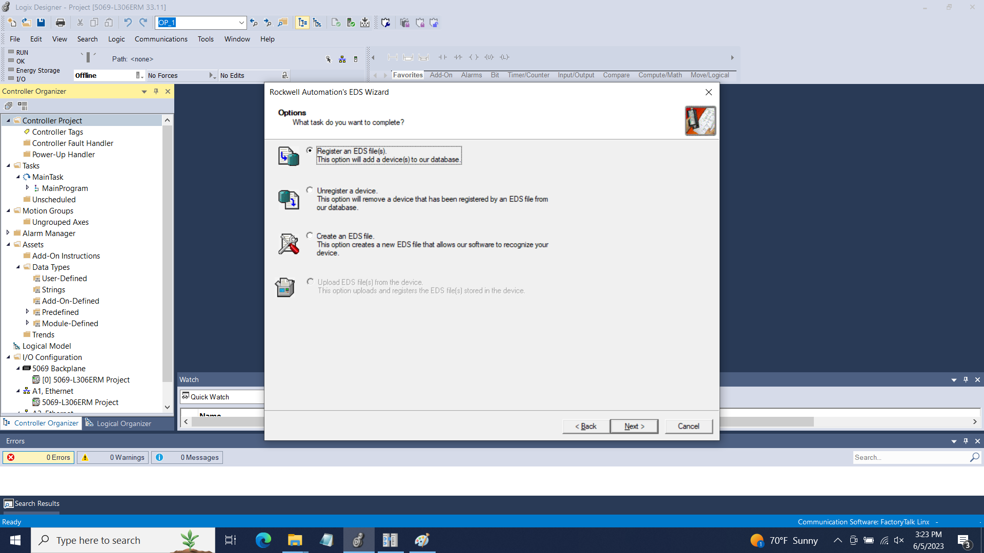
Click “Register an EDS file(s)” within the EDS Wizard when prompted:
-
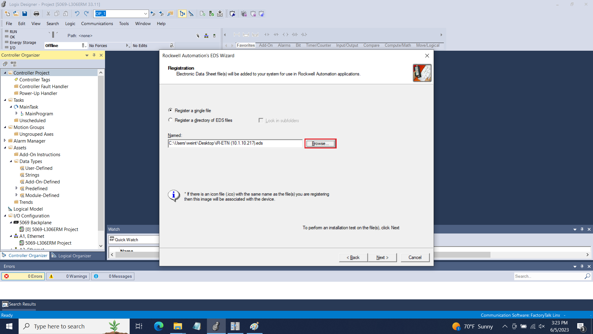
Locate the EDS file produced by EasyRemote IO:
-
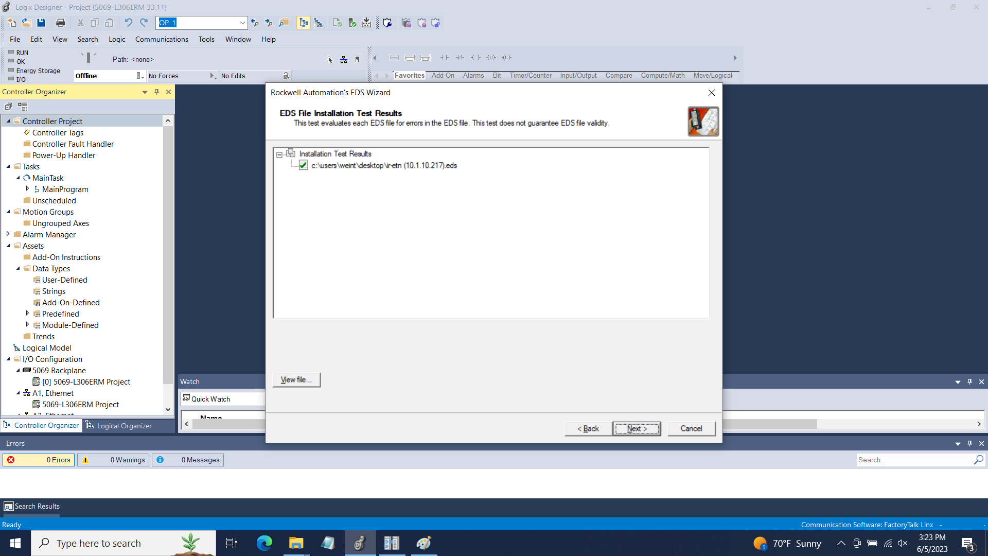
Follow the instructions to complete the installation:
-
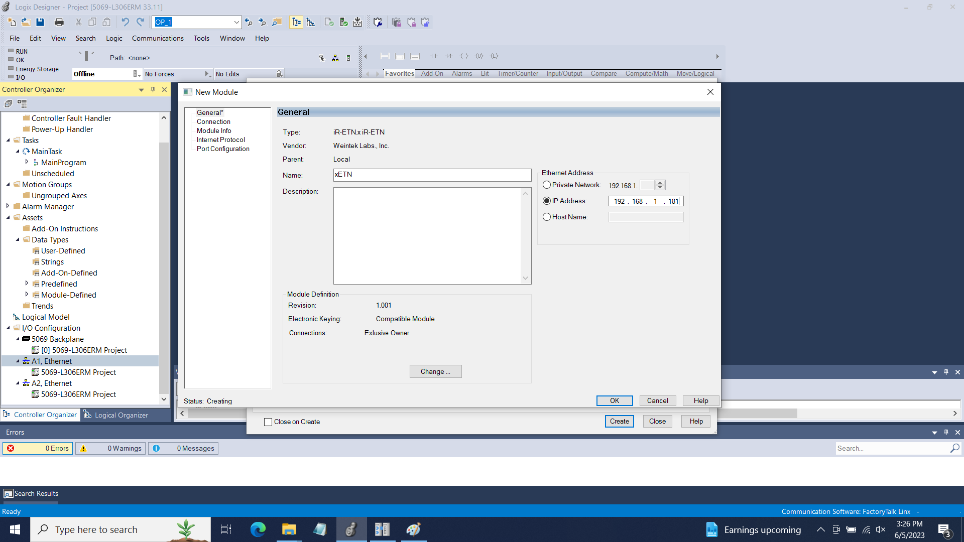
Once installed, add this device to your project by selecting “New Module…” under the connected port:
-
Configure the device “Name” and “IP Address”:
-
Click “OK” when finished.

Note: Rockwell Automation requires that vendors license their EDS for use in Logix Designer. Weintek’s iR-ETN EDS does not meet this requirement and as such the IO mapping will be added to a generic array of SINT called “data”.
-
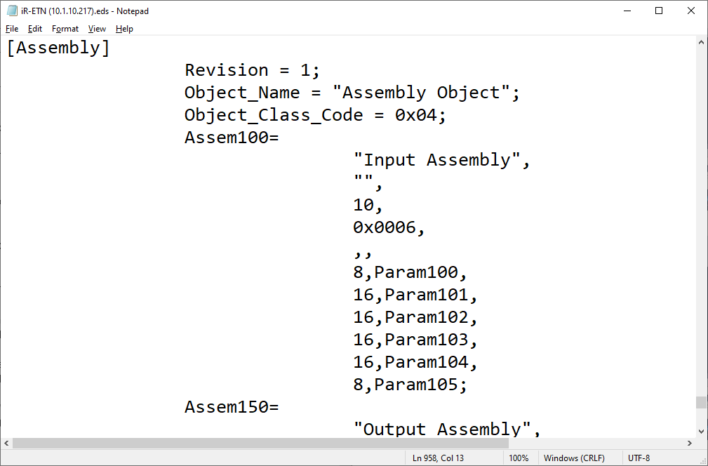
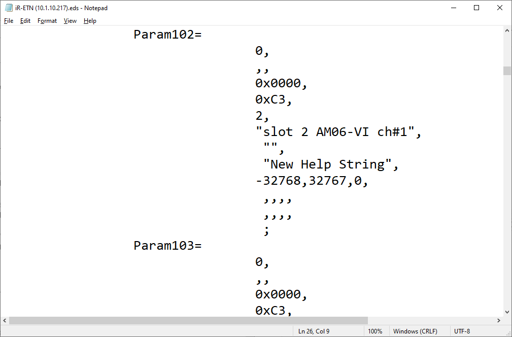
The generic array will be organized such that the inputs and outputs correspond to those listed within the “Assembly” section of the EDS file:
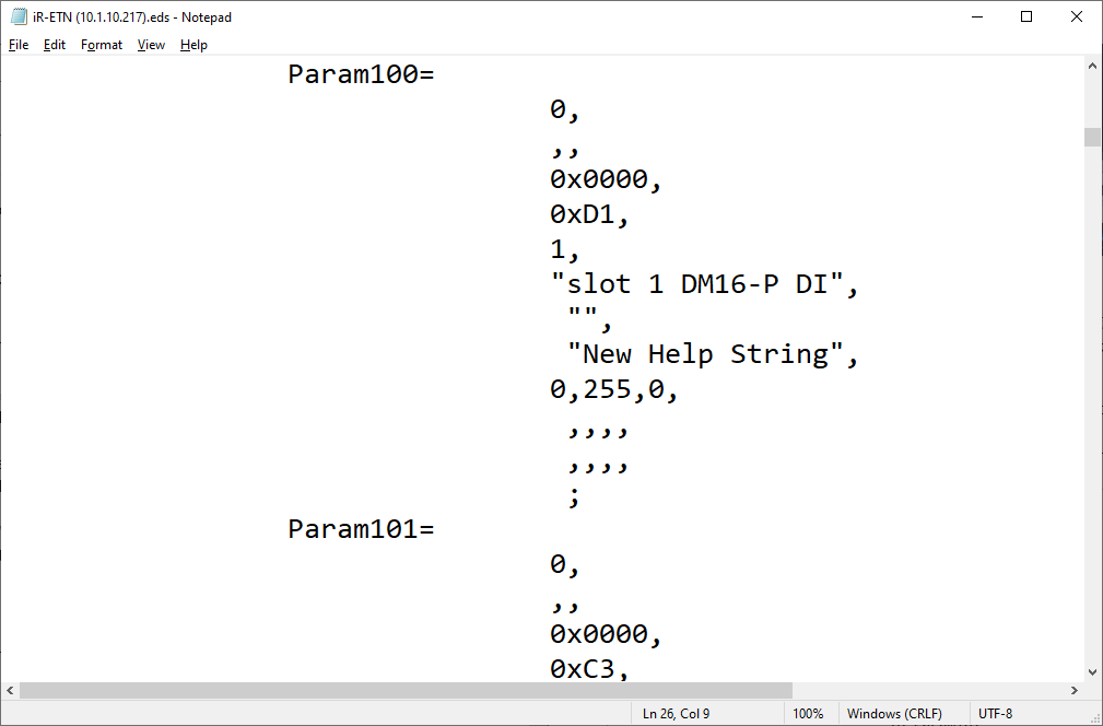
Note: The Input Assembly as viewed in notepad. Each “Param” is defined within the “Params” section of the file. The number adjacent to the “Param” is the size in bits meaning that “8, Param100” essentially means that the data within “Param100” is 8-bits in length.
Example: Param100 is defined as the digital inputs of the iR-DM16-P in slot 1.
Example: Param102 is defined as the channel 1 analog input of the iR-AM06-VI in slot 2.
-
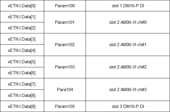
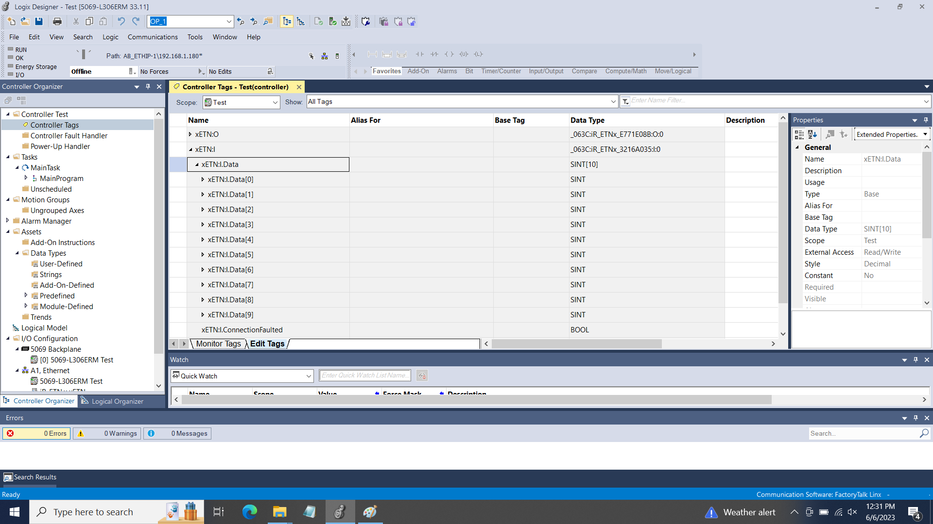
In this example, the address xETN:I.Data[0] corresponds with Param100, xETN:I.Data[1] and xETN:I.Data[2] correspond with Param101… etc:
Example: Within this example, the array of “Data” inputs corresponds with the following.
Notes:
- In Logix Designer, each device requires a unique EDS file. To add multiple iR-ETNs with different I/O configurations please define a “Generic Ethernet Module” for each additional device. For more information, please see section 3.2 within the iR-ETN/iR-ETN40R - EtherNet/IP Connection Guide.
Logix Designer is a trademark or registered trademark of Rockwell Automation.