Introduction:
Modbus TCP is a versatile protocol that is compatible with a wide range of industrial devices. Weintek’s implementation of Codesys supports Modbus TCP, but if you are new to Codesys the process of adding a Modbus TCP device can seem daunting. Within this post, you will learn how to add a Modbus TCP device to your Codesys project.
Important:
Weintek, like other vendors has validated certain drivers as compatible with our Codesys runtime. If you do not use the drivers and Codesys IDE that we recommend, the application may produce compilation and /or runtime errors that will be difficult to resolve.
| Device | Version |
|---|---|
| Codesys IDE | 3.5.15.50 [Download] |
| Ethernet adapter | 3.5.15.0 |
| Modbus TCP Master | 3.5.10.0 [Download] |
| Modbus TCP Slave | 3.5.10.0 [Download] |
Software Version:
Codesys IDE 3.5.15.50
Codesys package
Instructions:
Unlike the use of EtherNet/IP, Modbus TCP does not require you to update the the firmware of your device. However, you will need to install our Codesys package and an instance of the Codesys IDE.
Codesys install:
We highly recommend using Codesys 3.5.15.50 as the recommended Modbus TCP driver was validated within this version. To install Codesys, please see the section labeled “Where can I download Codesys?” in this post: Click here
Codesys project:
-
Connect your PC to the HMI as shown within this tutorial: Link
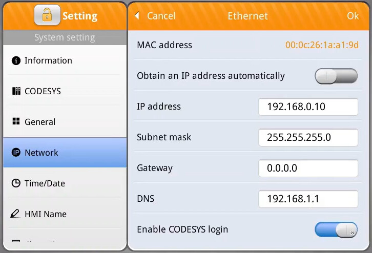
Note: The location of the “CODESYS login” function may vary by device type and firmware. The three possible locations of this option are shown below.- Note: The “CODESYS login” option may reside within the “Network” settings menu: Tutorial.
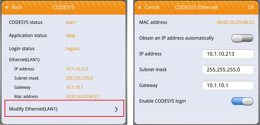
- Note: The “CODESYS login” option may reside within the “CODESYS” settings menu under the “Modify Ethernet(LAN1)” option: Tutorial.
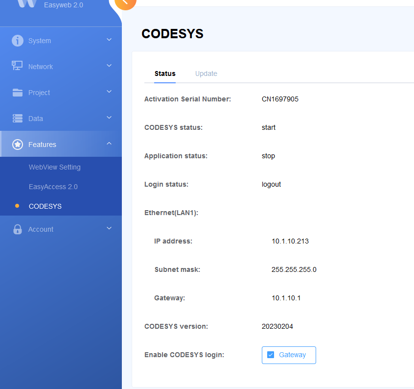
- Note: The “CODESYS login” option may reside within the “CODESYS” settings menu within the web server. Here is a link to a post in which we demonstrate how to access the HMI’s webserver: Link.
- Note: The “CODESYS login” option may reside within the “Network” settings menu: Tutorial.
-
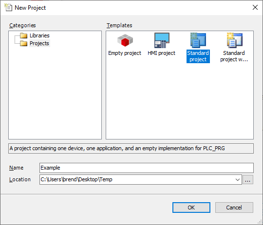
Open the Codesys IDE and create a new “Standard project” or open an existing project:
-
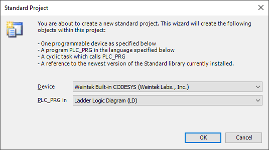
When prompted, ensure that “Weintek Built-in CODESYS” is selected:
-
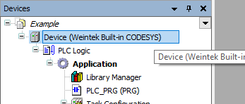
Within the project tree, double click “Device (Weintek Built-in CODESYS”:
-
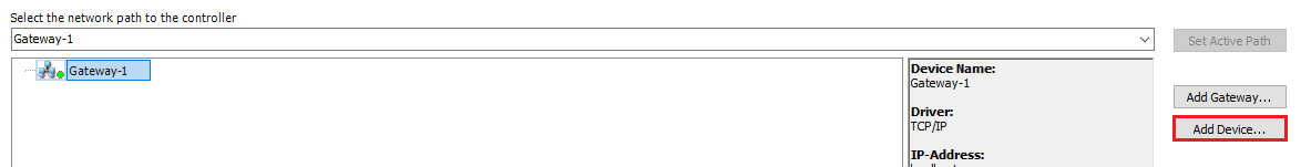
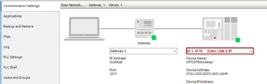
Select the “Gateway” and click “Add Device…”:
Note: If the “Device” tab appears as depicted below, please enter the HMI’s LAN-2 IP into the entry box on the far right and click the [Enter] key. When finished, proceed to step 9.
-
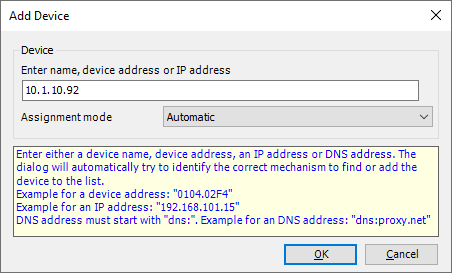
Within the following menu, enter the IP address of the HMI’s LAN-2 port:
-
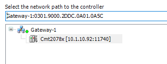
The HMI will append to the Gateway instance:
-
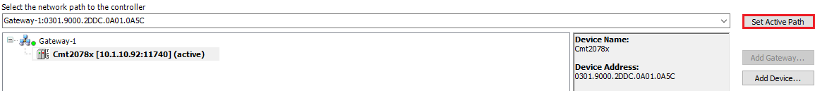
While the HMI is selected, click on the “Set Active Path…” button:
-
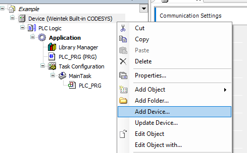
Within the project tree, right-click “Device (Weintek Built-in CODESYS)” and select “Add Device…”:
-
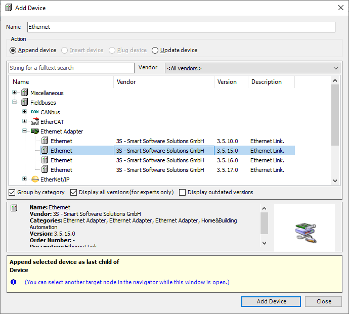
Within the following menu, select an “Ethernet” adapter with version 3.5.15.0 and click the “Add Device…” button in the bottom right corner:
Note: This driver should be appended to Weintek’s Codesys package, however, you may need to select the “Display all versions” check box to view this driver.
-
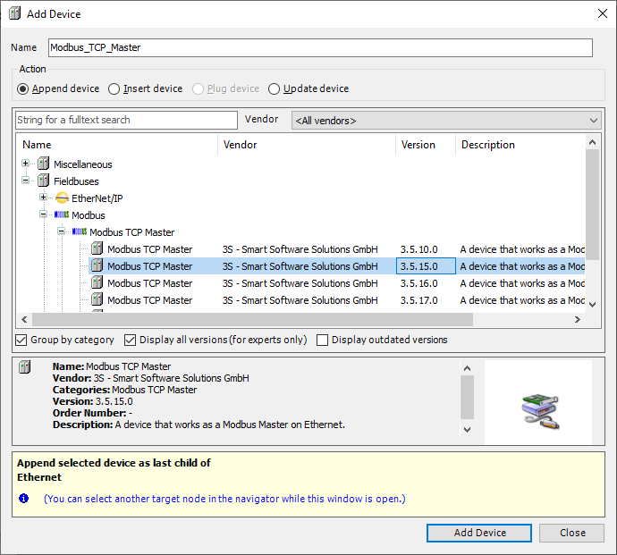
With the “Add Device…” menu still open, click on the “Ethernet” driver within the project tree and select an instance of a “Modbus TCP Master” with version 3.5.15.0 and click the “Add Device…” button in the bottom right corner:
Note: This driver should be appended to Weintek’s Codesys package, however, you may need to select the “Display all versions” check box to view this driver.
-
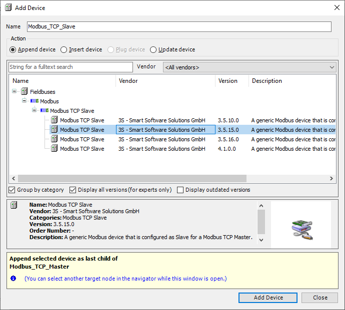
With the “Add Device…” menu still open, click on the “Modbus_TCP_Master” driver within the project tree and select an instance of a “Modbus TCP Slave” with version 3.5.15.0 and click the “Add Device…” button in the bottom right corner:
-
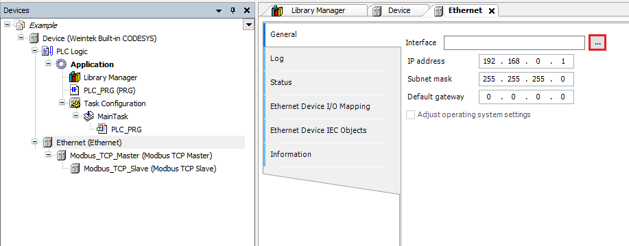
Double-click on the “Ethernet” device within the project tree and click on the ellipses within the following menu:
-
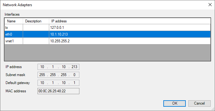
Within the “Network Adapters” menu, please select eth0 and click “OK”:
-
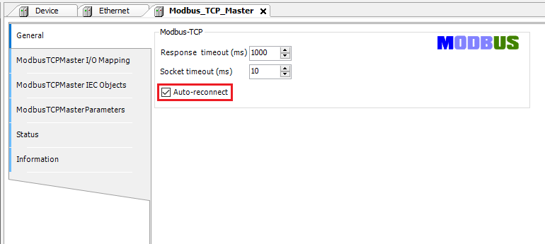
[Optional] Double-click on the “Modbus TCP Master” device within the project tree and ensure that “Auto-reconnect” is selected:
-
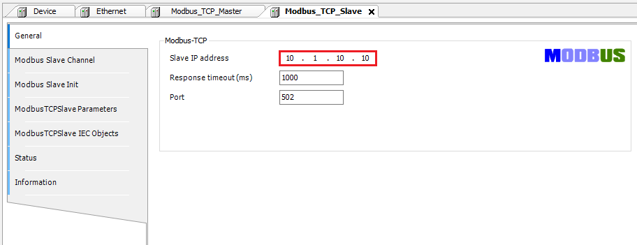
Double-click on the “Modbus TCP Slave” device within the project tree and configure the IP address within the “General” tab:
Note: By default the unit ID of the Modbus TCP slave is set to 255. If the device that you are attempting to write to utilizes a different unit ID, please use Modbus TCP Slave version 3.5.10.0 [Download].
-
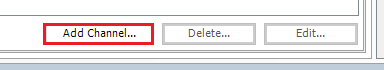
To map a variable to a Modbus address, you must configure each target address within the “Modbus Slave Channel” tab. To add a channel, select this tab and click on the “Add Channel…” button:
-
The Modbus addressing depends on the specifications of the target device and vendors may choose to display addresses as shown within the “Address” or “Equivalent” column:
Note: Some vendors may choose a one-based representation, in such cases an offset of 16#0000 with “Write Single Register” selected will map to register 4x-1 or 40001 within the target device.
| Codesys | Mapping | ||||||
|---|---|---|---|---|---|---|---|
| Access Type | Offset | Address | Equivalent | ||||
| One-based | Zero-based | ||||||
| Write Single Register | 16#0000 | 40001 | 4x-1 | 4x-0 | |||
| Write Multiple Registers | 16#0000 | 40001 | 4x-1 | 4x-0 | |||
| Write Single Coil | 16#0000 | 1 | 0x-1 | 0x-0 | |||
| Write Multiple Coils | 16#0000 | 1 | 0x-1 | 0x-0 | |||
| Read Holding Registers | 16#0000 | 40001 | 4x-1 | 4x-0 | |||
| Read Input Registers | 16#0000 | 30001 | 3x-1 | 3x-0 | |||
| Read Discrete Inputs | 16#0000 | 10001 | 1x-1 | 1x-0 | |||
| Read Coil | 16#0000 | 1 | 0x-1 | 0x-0 |
-
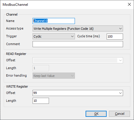
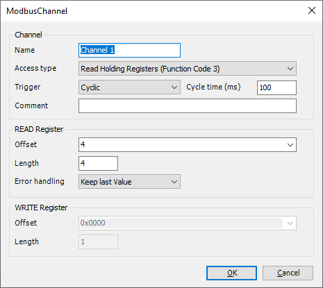
Configure the channel such that it maps to the desired Modbus register:
Note: This channel will allow us to write to 4x-100 ~ 4x-109 (One-based).
Note: This channel will allow us to read from 4x-5~ 4x-9 (One-based ).
-
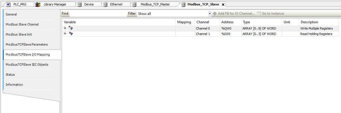
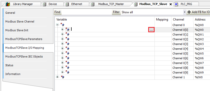
To map a variable to a Modbus address select the “ModbusTCPSlave I/O Mapping” tab:
-
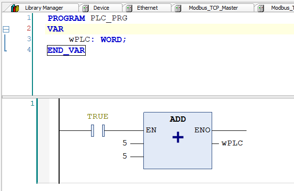
To map a variable to an I/O point, declare the variable within a POU, GVL, or PVL:
Note: Here is an example in which we declare a variable within a POU and map it to I/O within a Modbus TCP slave: 4:32.
-
Once a variable has been declared, select the “ModbusTCPSlave I/O Mapping” tab within the Modbus TCP Slave device and double-click next to the desired I/O point in the “Variable” column. When prompted, click on the ellipses:
-
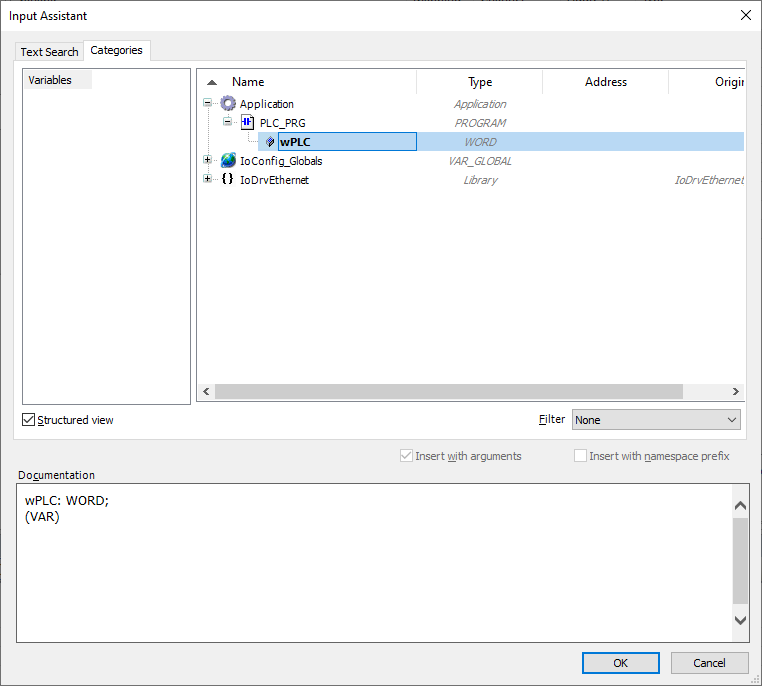
Ensure that the desired project variable is selected and click “OK” to map this variable to the I/O point:
Note: If the variable mapped to an IO point is not used within the ladder, the data within the IO point will not be polled by the PLC.
-
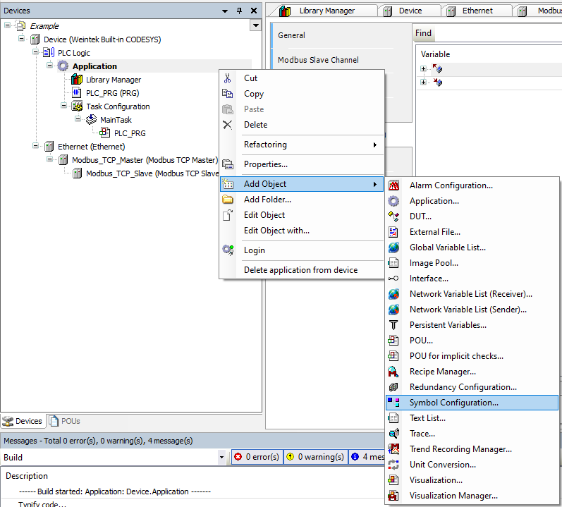
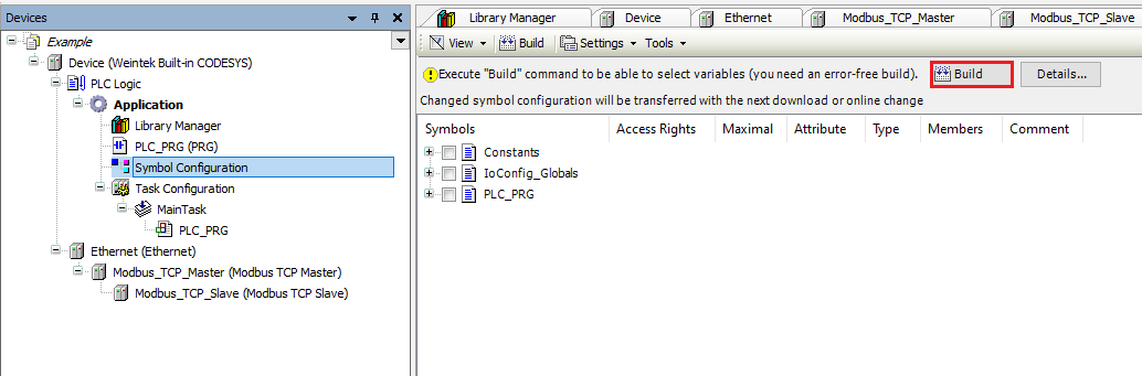
When the project is finished, right-click on “Application” and within the “Add Object” list click “Symbol Configuration…”:
-
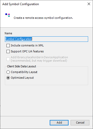
When prompted, click “Add”:
-
Select “Build” within the following menu to verify that the application is error-free:
-
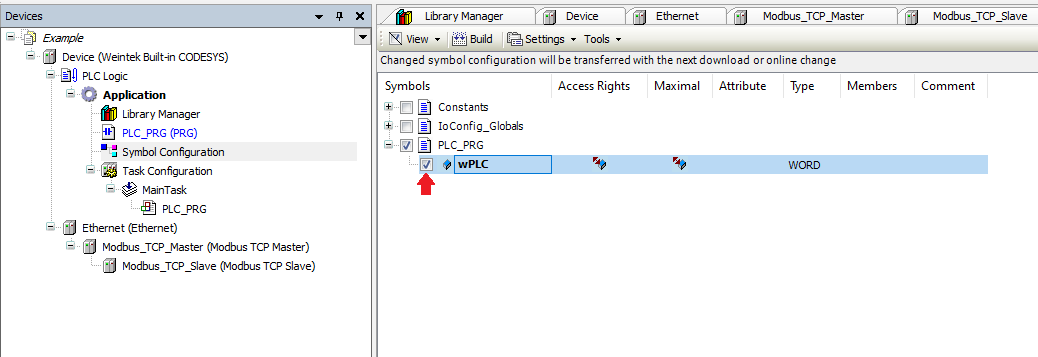
Ensure that each tag that you wish to export is selected within this list:
-
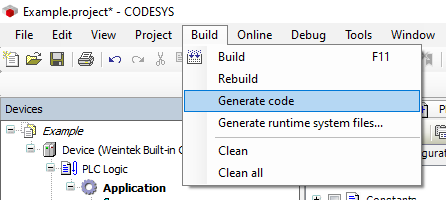
Within the “Build” tab, click on “Generate code” and an .xml file called “[PROJECT NAME].Device.Application.xml” will be saved within the same folder as the project file. We will use this file to import tags into EasyBuilder Pro:
Note: New tags that do not automatically import into EasyBuilder Pro. If you create a new tag within your Codesys project and wish to access it from EasyBuilder Pro, ensure that each tag you wish to export is selected before selecting “Generate Code”. Then, import the .xml file into EasyBuilder Pro.
-
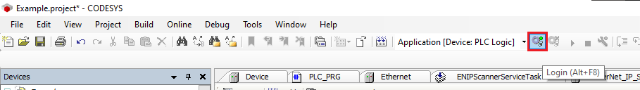
Before you save and exit the application, please click the “Login” button to download this project to the HMI:
-
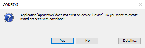
If prompted to “proceed with download” click “Yes”:
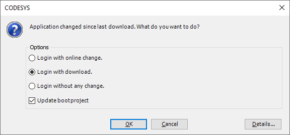
Note: Subsequent changes may display the following menu. If prompted, ensure that “Login with download” and “Update bootproject” are enabled.
-
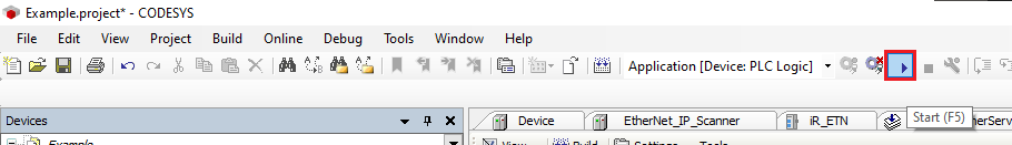
Click the “Start” button to place the Codesys application in “RUN” mode:
EasyBuilder Pro:
-
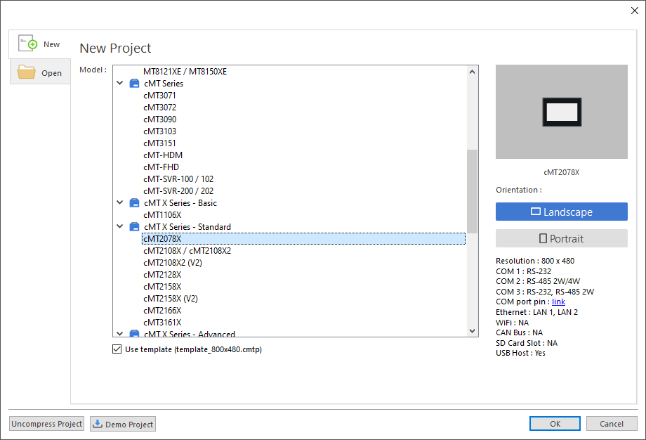
Open an instance of EasyBuilder Pro and select the HMI that you will use within this application:
-
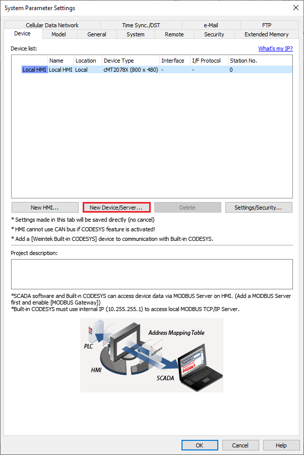
Once open, select the “New Device/Server” button within the “System Parameters”:
-
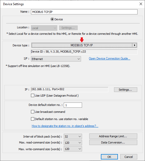
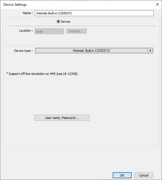
Within the following menu, click on the center of the “Device type” drop-down list:
-
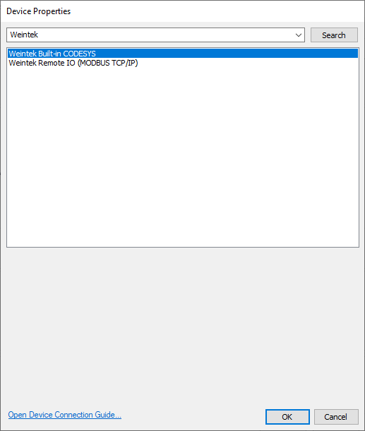
A popup dialog will appear, within this dialog please search for and select the “Weintek Built-in CODESYS” driver and then click “OK”:
-
Configure any additional settings and then click “OK” once more:
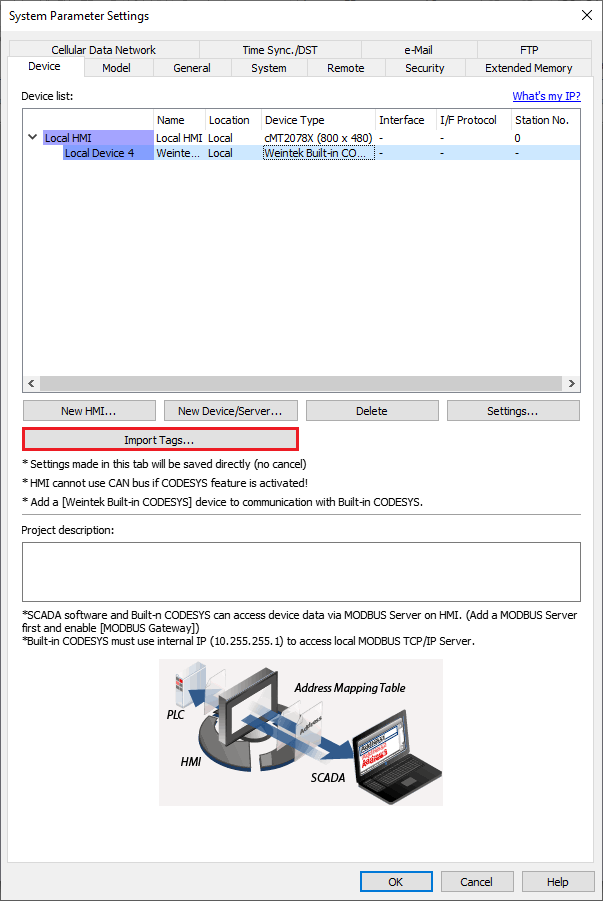
-
While the “Weintek Built-in CODESYS” driver is selected click on the “Import Tags…” button:
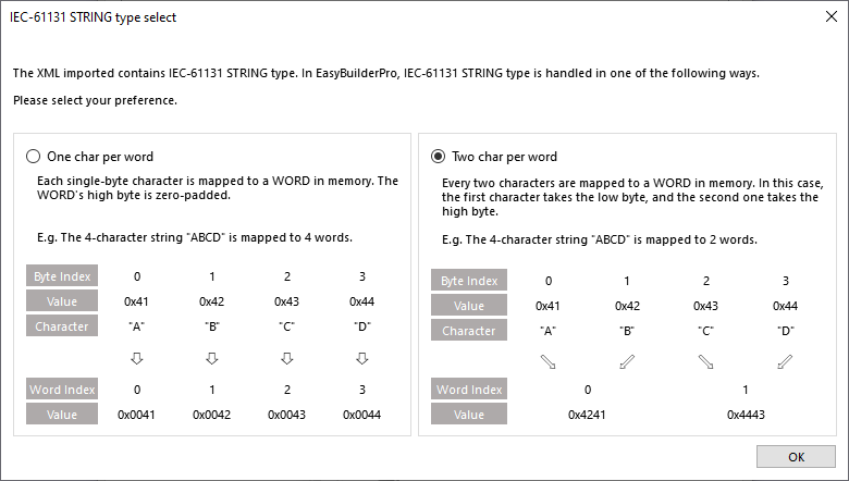
-
Within the following menu, select either “One char per word” or “Two char per word” depending on your preference of STRING representation, and click “OK”:
-
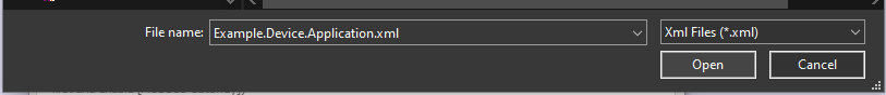
Locate the .xml tag file titled “[PROJECT NAME].Device.Application.xml” and click “Open”:
-
The following popup will display, click “OK”:
\
-
It is now possible to reference objects by selecting a tag within an object that corresponds with its data type. Here is a link to a tutorial in which we demonstrate how to assign an object to a tag and download this project to your HMI: 7:09
Note: Within EasyBuilder Pro tags can be viewed and selected within an object. There is no utility that allows you to view all tags simultaneously.