Introduction:
Weintek’s implementation of Codesys supports Modbus TCP, EtherCAT, CANopen, and EtherNet/IP. However, certain applications may require the use of non-native or legacy protocols like Modbus RTU. In this scenario, we can utilize the HMI’s internal Modbus TCP server to allow Codesys access to many of the 400+ industrial protocols available within EasyBuilder Pro. Within this post, you will learn the steps required to support non-native protocols.
Important:
Weintek, like other vendors has validated certain drivers as compatible with our Codesys runtime. If you do not use the drivers and Codesys IDE that we recommend, the application may produce compilation and /or runtime errors that will be difficult to resolve.
| Device | Version |
|---|---|
| Codesys IDE | 3.5.15.50 [Download] |
| Ethernet adapter | 3.5.15.0 |
| Modbus TCP Master | 3.5.10.0 [Download] |
| Modbus TCP Slave | 3.5.10.0 [Download] |
Note: Click here for installation instructions.
Software Version:
Codesys IDE 3.5.15.50
Codesys package
[Optional] Codesys firmware
Instructions:
Codesys install:
We highly recommend using Codesys 3.5.15.50 as the recommended Modbus TCP driver was validated within this version. To install Codesys, please see the section labeled “Where can I download Codesys?” in this post: Click here
Concept:
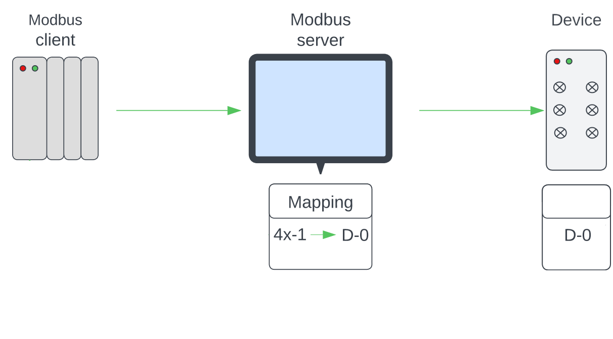
“Modbus server” in the context of this post, is a driver within EasyBuilder Pro that will allow us to associate a register or tag in an external device with a Modbus register. The process of building this association is called “mapping”. After a register or tag has been “mapped” to a Modbus register, a Modbus client can read or write data within this tag by sending a request to the Modbus server. This process is depicted below:
Note: In this example, register “D-0” within the “Device” is mapped to register “4x-1” in the Modbus server. When the Modbus client sends a read request for 4x-1, the Modbus server relays this request to the device and data within D-0 is returned.
Although Modbus may seem complex, this protocol is actually quite simple. Within this example, we define registers you may find within any Modbus device:
Note: Some Modbus vendors use different terminology like 40000 instead of 4x. Nevertheless, these registers are equivalent such that 40101 = 4x-101.
| Data type | Address | Access type | Description |
|---|---|---|---|
| Bit | 0x | Read/Write | Output coil |
| Bit | 1x | Read only | Input contact |
| Word | 3x | Read only | Analog input |
| Word | 4x | Read/Write | Analog output |
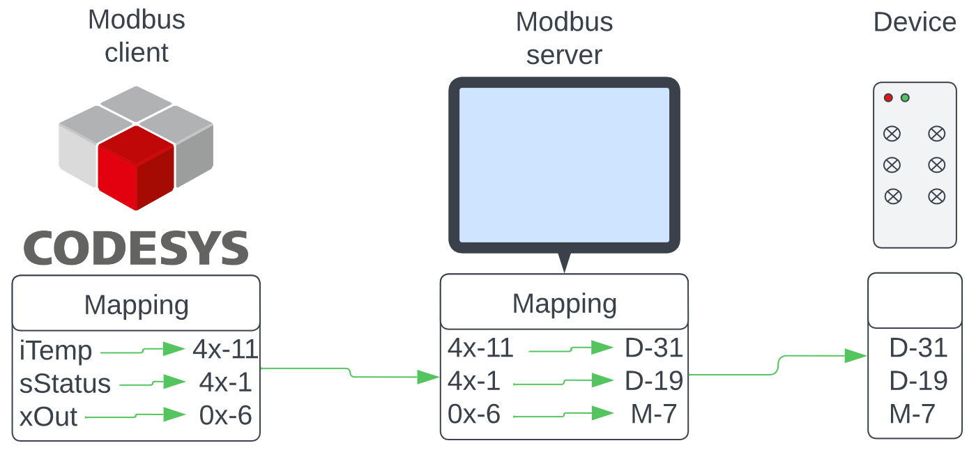
In order to make use of “mapped” registers, we must configure Codesys to act as a Modbus client. This process is relatively simple, but it does require that you define the “channel” mapping in Codesys as well. An example of this architecture is depicted below:
Note: iTemp and sStatus are Codesys project variables that have been mapped to Modbus registers. To access data, Codesys sends a request to the HMI labeled “Modbus server” in this example. The HMI relays this request to the “Device” such that iTemp now reads D-31 and sStatus D-19.
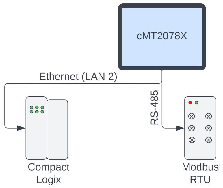
Wiring:
When Codesys variables are “mapped” to the Modbus server within EasyBuilder Pro, communication will be routed through COM ports assigned to the HMI. These include serial COM 1 ~ 3 and Ethernet LAN 2.
EasyBuilder Pro:
-
Connect your PC to the HMI’s LAN 2 port and ensure that the HMI and PC are set to the same IP subnet: Tutorial
-
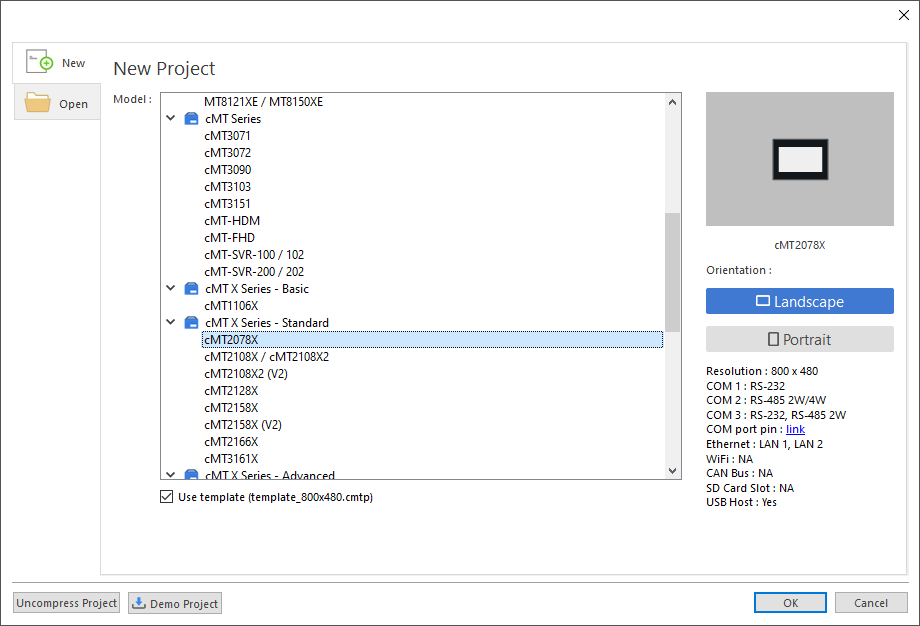
Open an instance of EasyBuilder Pro and select the HMI that you will use within this application:
-
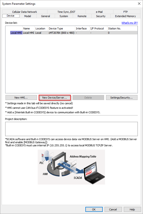
Once open, select the “New Device/Server” button within the “System Parameters”:
-
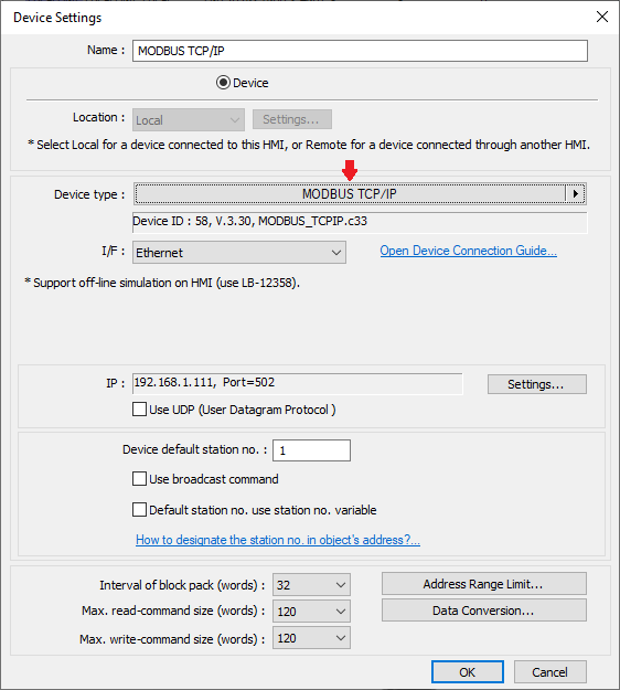
Within the following menu, click on the center of the “Device type” drop-down list:
-
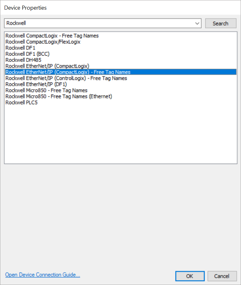
A popup dialog will appear, within this dialog please search for and select a driver that will allow the HMI to communicate with the external device:
Note: To find a list of supported devices and the recommended drivers, please see this post.
-
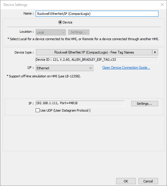
Configure any additional settings and then click “OK”:
-
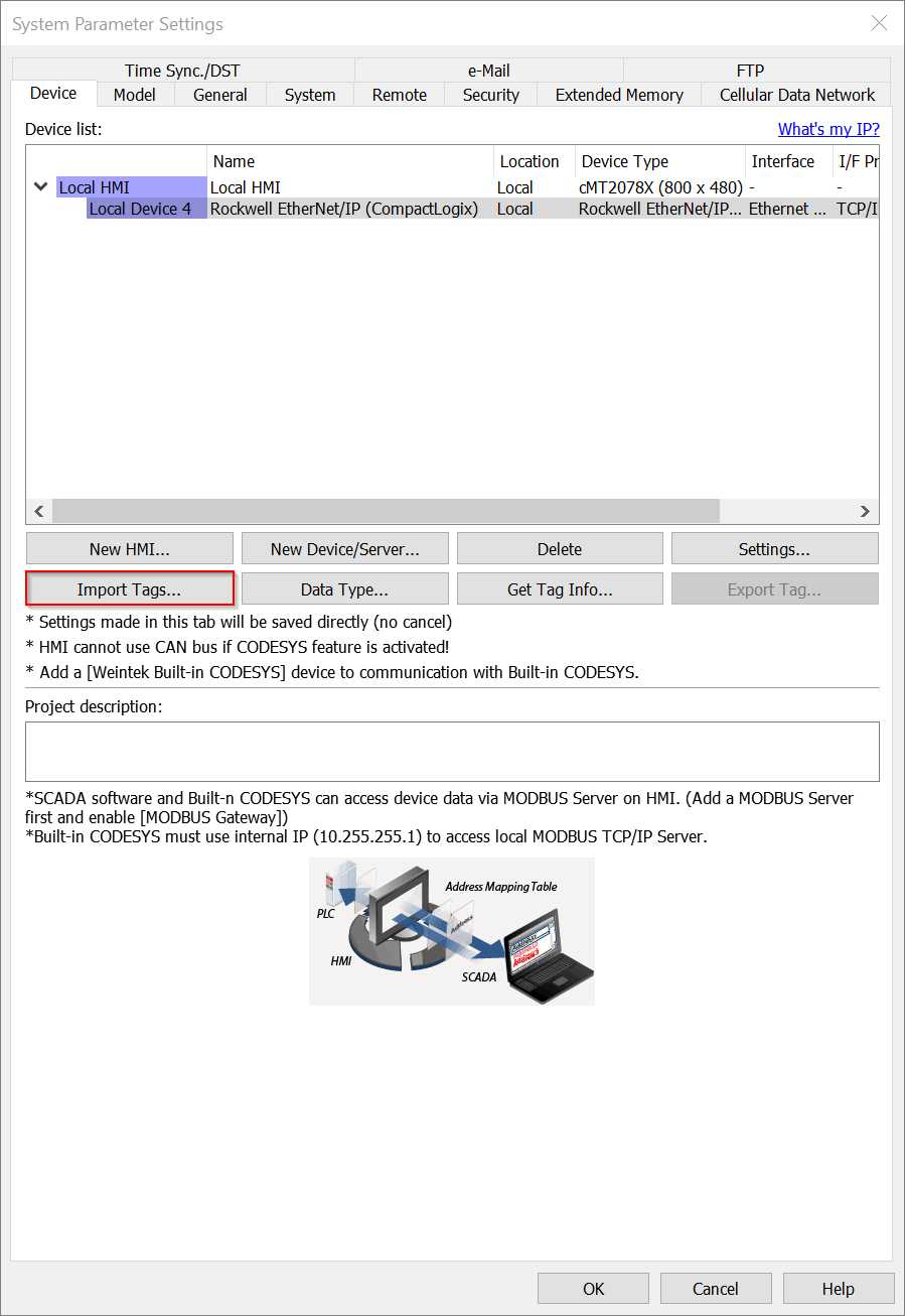
[Optional] If the HMI will communicate with a tag-based device like a Compact Logix, ensure that this driver is selected within the “Device list” and click the “Import Tags…” or “Tag manager” button to add the required tags to your project:
Note: The tag-import process varies by device, but this process is described within the “PLC Connection Guide” that corresponds with the communication driver you’ve selected.
-
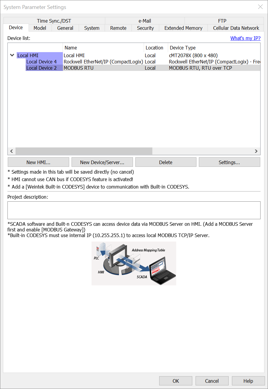
If you are mapping Codesys variables to more than one device, repeat steps 3-7 to define all additional drivers:
Note: In this example, I’ve added a Modbus RTU device as well.
-
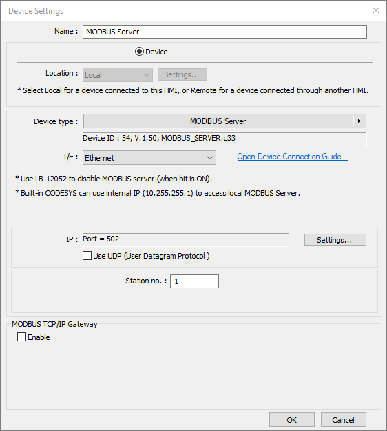
When finished, select the “New Device/Server…” button and add an instance of the “Modbus Server” driver:
-
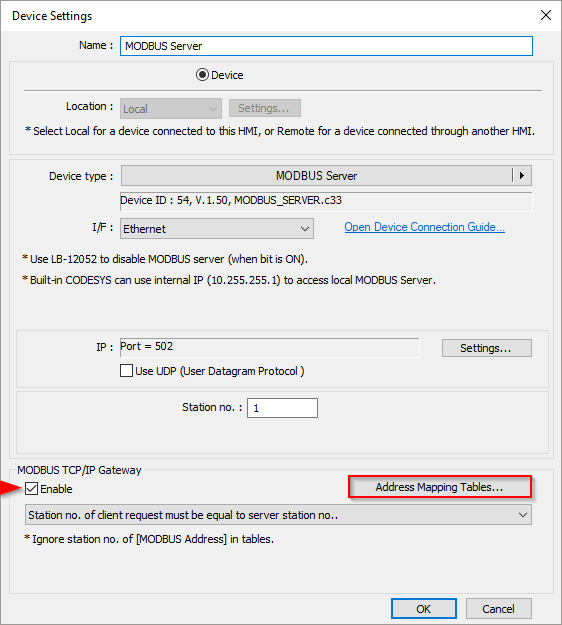
Within the “Device Settings” menu, enable “Modbus TCP/IP Gateway” and click on the “Address Mapping Tables…” button:
-
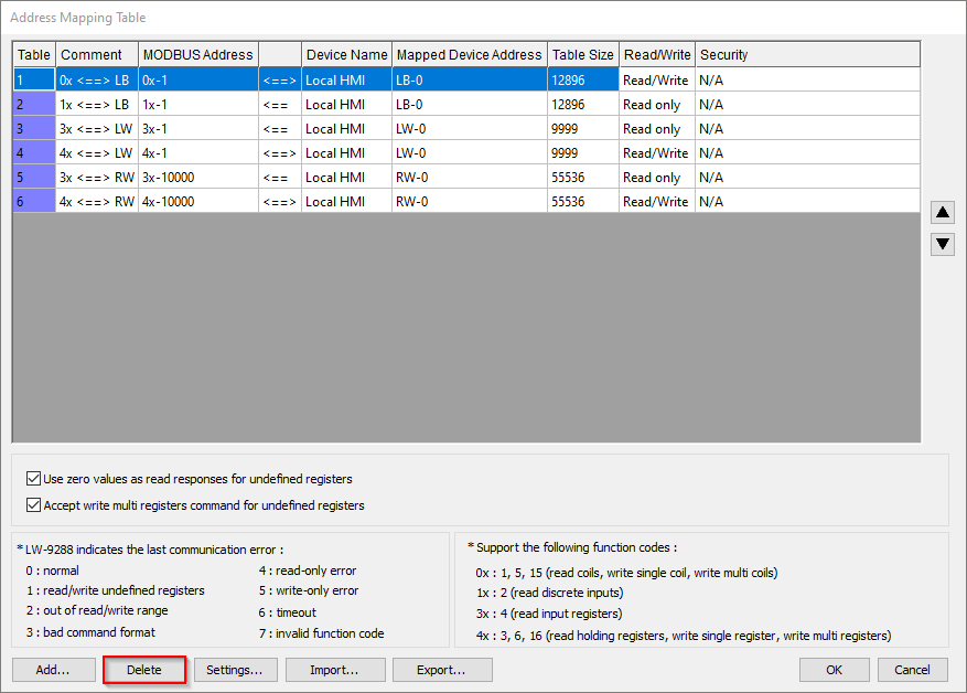
Within the “Address Mapping Table” popup, click the “Delete” button to remove any existing tables:
-
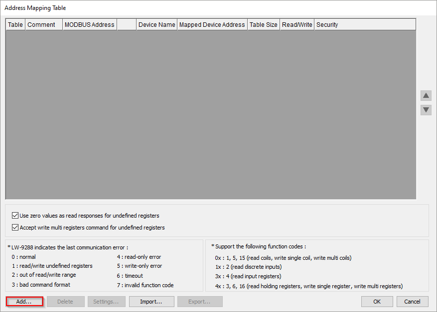
Click the “Add” button to add a table:
-
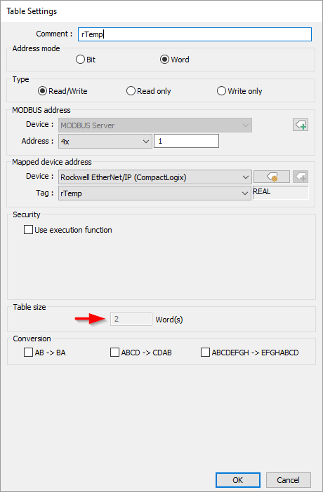
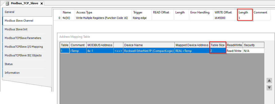
Define the “Comment” which denotes the name of this table and configure the “Address mode” to either “Bit” or “Word”. The “Address mode” determines what “Address” types (e.g., 0x or 4x) will be accessible. In addition, this setting determines what “Tags” will be displayed within the “Tag” drop-down list:
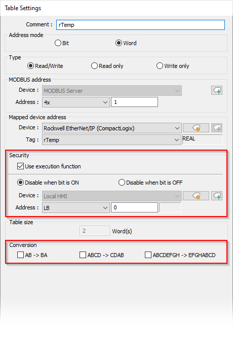
Note: When mapping a Modbus register to a non-array tag the “Table size” is predefined. In this example, Modbus register 4x-1 is mapped to a tag of type REAL. Since a REAL data type is 32-bits in size, data within this tag will occupy both 4x-1 and 4x-2 as each Modbus register is 16-bits in size.
-
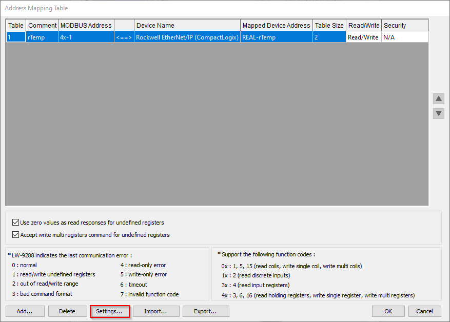
When finished, click “OK” and while added, the “Settings…” button can be used to modify this table:
-
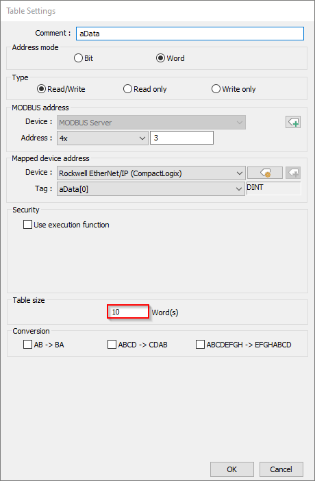
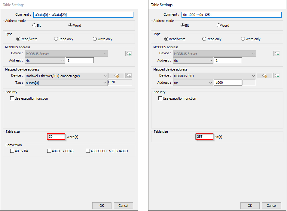
To add an array, specify the “Table size” in bits or “words” as in this example:
-
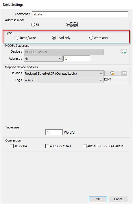
The “Type” determines what client requests will be allowed by this table. Within this example, we have defined this array as “Read only”:
Note: 3x and 1x registers are “Read only” by definition.
-
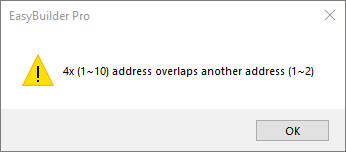
In step 16, we defined the “Modbus address” as 4x-1. However, this address was already utilized in step 13. If you attempt to use an address that is already “mapped” to another tag or register an “address overlap” message will display and this table will not be added to the gateway:
-
All remaining “Table settings” are defined below:
| Setting | Description |
|---|---|
| Conversion | While “Address mode” set to Word, the “Conversion” options allow you to swap bit positions such that data is transmitted in the correct format. AB->BA swaps the high and low-byte of a value that is 16-bits in size when checked. ABCD->CDAB swaps the high and low-word of a value that is 32-bits in size when checked. ABCDEFGH->EFGHABCD swaps the high and low double-word of a value that is 64-bits in size when checked. |
| Security | While the “Type” is set to Write only or Read/Write you can define a Boolean variable to prevent a Modbus TCP client from writing data in this mapping table. |
- When finished, click “Ok” to save the table configuration:
Note: When “Use zero values as read responses for undefined registers” is enabled, the Modbus gateway will allow a client to read undefined registers but the value returned will be 0. When “Accept write multi registers command for undefined registers” is enabled, the HMI will allow the Modbus client to “write” to registers that were not used within a mapping table.
Tips:
-
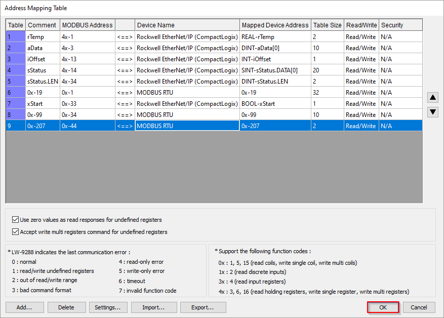
For ease of development it is highly-recommended that Modbus mapping is defined using consecutive addressing. Within a large project, this will greatly reduce the number of channels defined in Codesys and create a system that is both easy to maintain and upgrade.
Note: Within the table below, 4x-1 ~ 4x-35 are mapped to variables within the Compact Logix. The mapping is consecutive such that within the range of 4x-1 ~ 4x-35 there are no unused portions of Modbus memory. The same is true for 0x mapping.
-
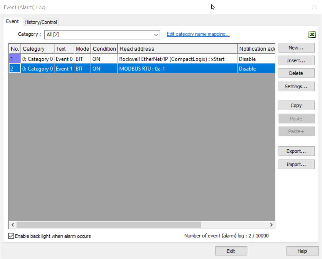
Communication must be validated on the HMI prior to “mapping” Modbus variables within Codesys. In addition, most drivers require that at least one Event (Alarm) or UI object addressed to a valid register exist in order for the HMI to “build” communication with the device:
Note: Within the application below, we’ve added an event alarm addressed to 0x-1 within the Modbus RTU device and xStart within the Rockwell device to ensure that the HMI “builds” communication with each device.
-
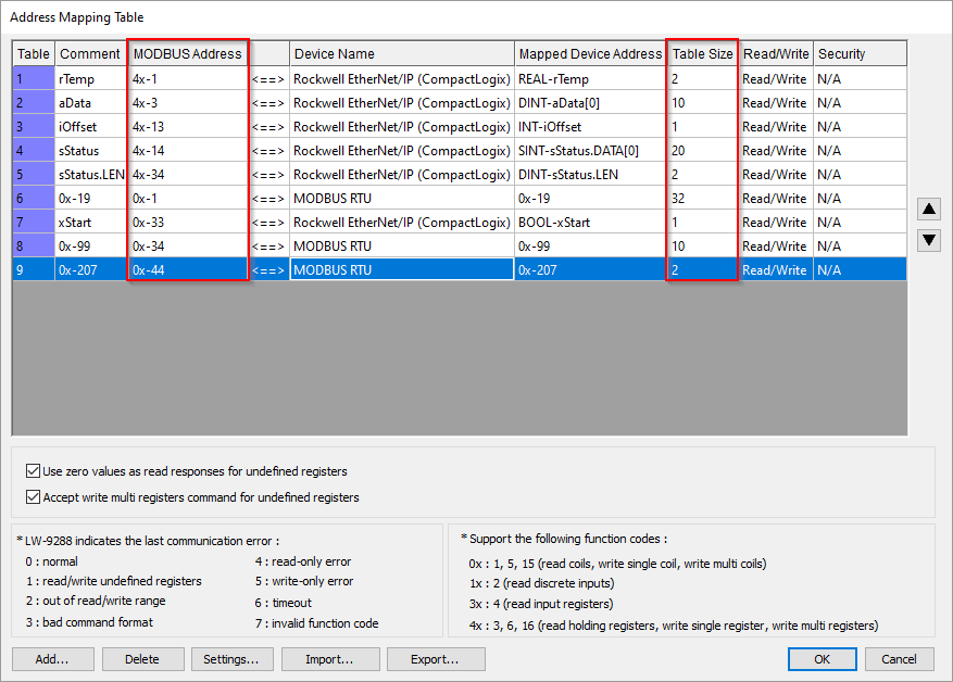
To optimize communication we highly-recommended mapping tables to array types or a “block” of contiguous registers. Using arrays or register “blocks” will reduce the number of requests sent by the HMI. Here is an example:
Note: When the HMI polls data from the “Rockwell” device in the image below, it may do so by sending only one request or packet to the controller. Therefore, even if we only needed to read aData[0], aData[11], and aData[29] this method of mapping may still be more efficient than requesting each of these 3 elements individually.
Codesys project:
-
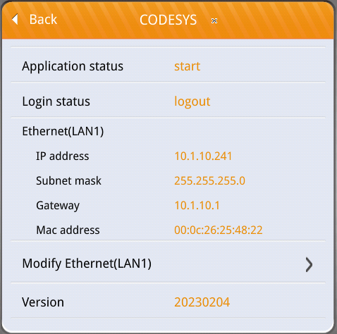
Connect your PC to the HMI’s LAN 1 port and ensure that the HMI and PC are set to the same IP subnet:
Note: The IP address of Codesys may be configured by clicking “Modify Ethernet(LAN1)” within the “Codesys” tab of the HMI’s settings menu.
-
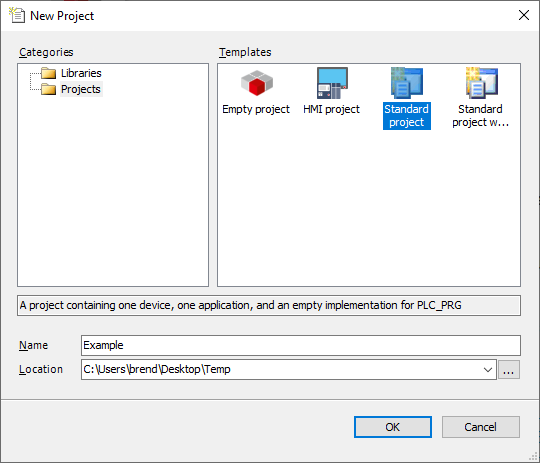
Open the Codesys IDE and create a new “Standard project” or open an existing project:
-
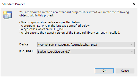
When prompted, ensure that “Weintek Built-in CODESYS” is selected:
-
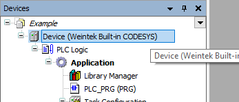
Within the project tree, double click “Device (Weintek Built-in CODESYS”:
-
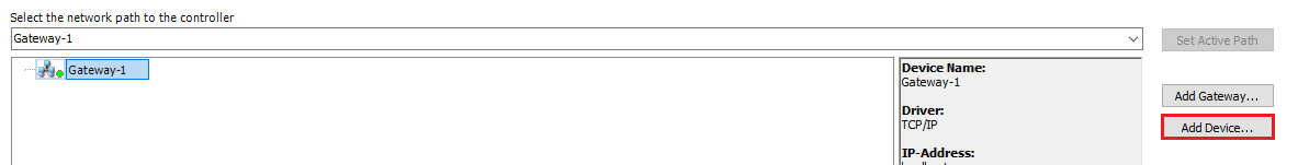
Select the “Gateway” and click “Add Device…”:
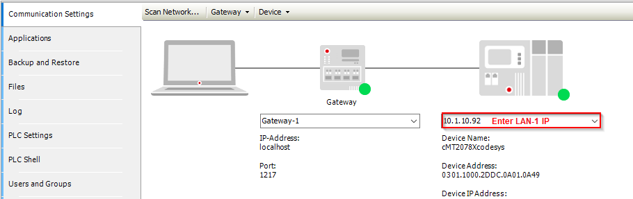
Note: If the “Device” tab appears as depicted below, please enter the HMI’s LAN-1 IP into the entry box on the far right and click the [Enter] key. When finished, proceed to step 9.
-
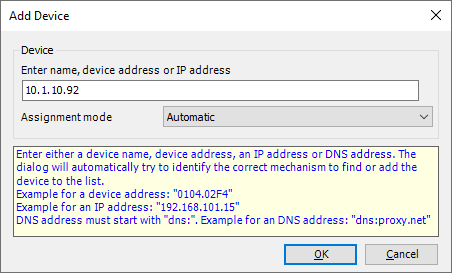
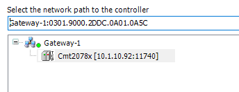
Within the following menu, enter the IP address of the HMI’s LAN-1 port:
-
The HMI will append to the Gateway instance:
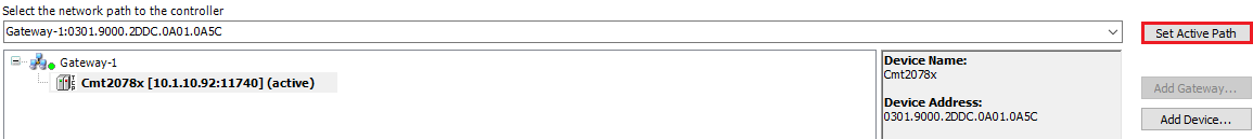
-
While the HMI is selected, click on the “Set Active Path…” button:
-
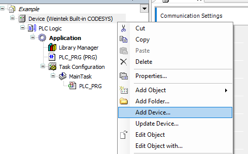
Within the project tree, right-click “Device (Weintek Built-in CODESYS)” and select “Add Device…”:
-
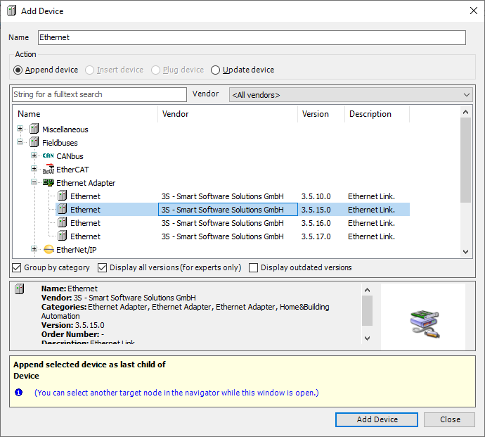
Within the following menu, select an “Ethernet” adapter with version 3.5.15.0 and click the “Add Device…” button in the bottom right corner:
Note: This driver should be appended to Weintek’s Codesys package, however, you may need to select the “Display all versions” check box to view this driver.
-
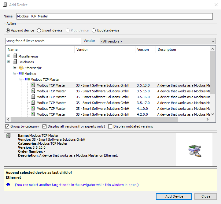
With the “Add Device…” menu still open, click on the “Ethernet” driver within the project tree and select an instance of a “Modbus TCP Master” with version 3.5.10.0 and click the “Add Device…” button in the bottom right corner:
*Note: Select the “Display all versions” check box to view this driver.
-
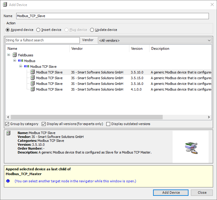
With the “Add Device…” menu still open, click on the “Modbus_TCP_Master” driver within the project tree and select an instance of a “Modbus TCP Slave” with version 3.5.10.0 and click the “Add Device…” button in the bottom right corner:
*Note: Select the “Display all versions” check box to view this driver.
-
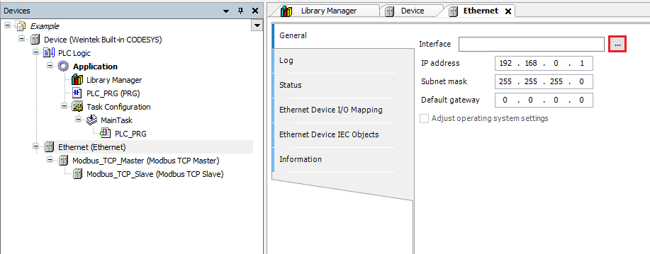
Double-click the “Ethernet” device within the project tree and click on the ellipses within the following menu:
-
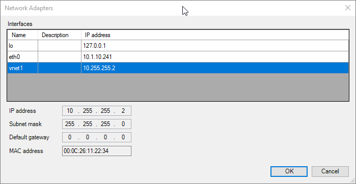
Within the “Network Adapters” menu, please select vnet1 and click “OK”:
Note: 10.255.255.2 is the internal IP address of Codesys.
-
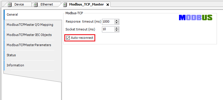
Double-click the “Modbus TCP Master” device within the project tree and ensure that “Auto-reconnect” is selected:
-
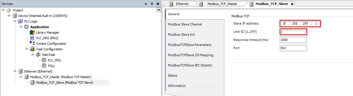
Double-click the “Modbus TCP Slave” device within the project tree and configure the IP address within the “General” tab to 10.255.255.1 and the “Unit ID” to 1:
Note: 10.255.255.1 is the internal IP address of the HMI. The “Unit ID” should match the “Station number” of the “Modbus Server” within EasyBuilder Pro.
-
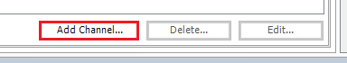
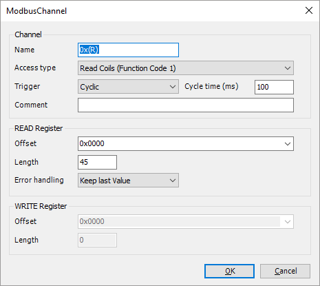
To map a variable to a Modbus address, you must configure each target address within the “Modbus Slave Channel” tab. To add a channel, select this tab and click the “Add Channel…” button:
-
The Modbus addressing depends on the specifications of the target device. In the context of this post it is important to note that Codesys uses a 0-based addressing format. This means that the “Offset” of a “ModbusChannel”, which correlates with the first Modbus address in a request, will differ from what is set within the HMI’s address mapping tables by ‘1’. The address correlation is defined below:
| Codesys | HMI | Note | ||||
|---|---|---|---|---|---|---|
| Access Type | Function code | Offset | Address | |||
| Write Single Register | 6 | 16#0000 | 4x-1 | |||
| Write Multiple Registers | 16 | 16#0000 | 4x-1 | |||
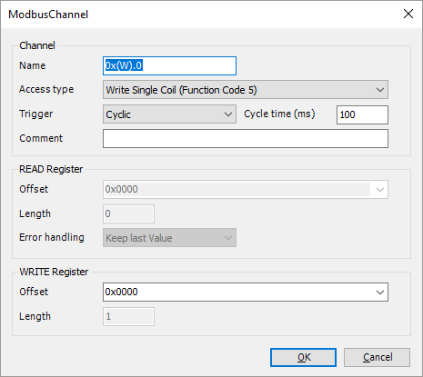
| Write Single Coil | 5 | 16#0000 | 0x-1 | |||
| Write Multiple Coils | 15 | 16#0000 | 0x-1 | Only compatible with HMI LB memory | ||
| Read Holding Registers | 3 | 16#0000 | 4x-1 | |||
| Read Input Registers | 4 | 16#0000 | 3x-1 | |||
| Read Discrete Inputs | 2 | 16#0000 | 1x-1 | |||
| Read Coil | 1 | 16#0000 | 0x-1 |
-
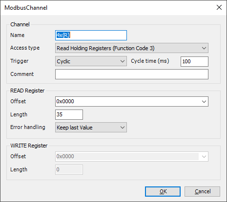
Configure the “channel” such that it maps to the desired Modbus mapping table(s). If you’ve designed your project using consecutive addresses (see tips), one “channel” within Codesys may be used to map variables within multiple Modbus mapping tables:
Note: This channel will allow us to read from 4x-1~ 4x-35 which corresponds with tables 1 ~ 5 depicted in step 19.
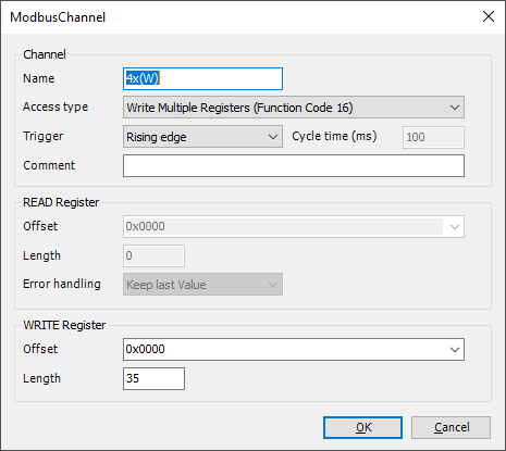
Note: Similarly, this channel will allow us to write to 4x-1~ 4x-35. However, the “Trigger” mode was set to “Rising edge” in order to prevent unintended overwrite.
Note: This channel will allow us to read from 0x-1~ 0x-45 which corresponds with tables 6 ~9 depicted in step 19.
Note: This channel will allow us to write to 0x-1 which corresponds with 0x-19 of the Modbus RTU device as defined in tables 6 and depicted in step 19.
-
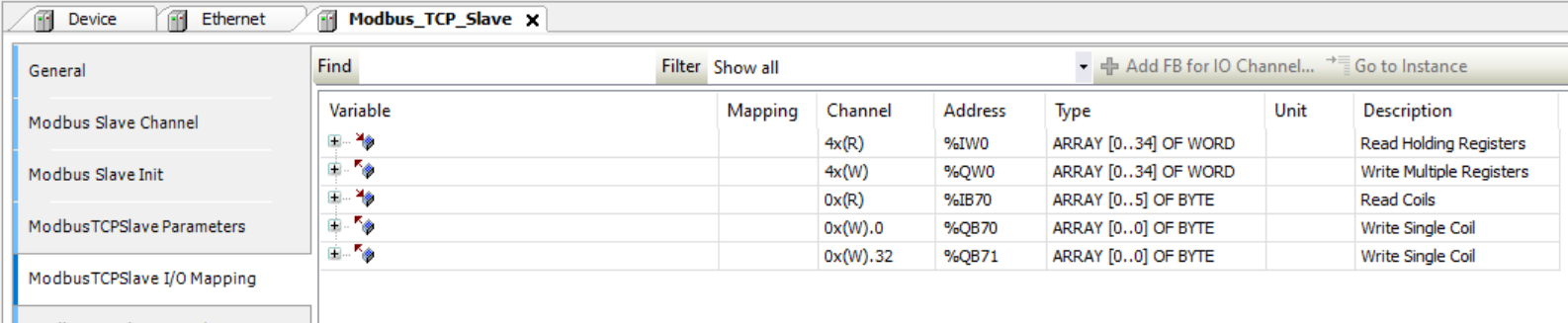
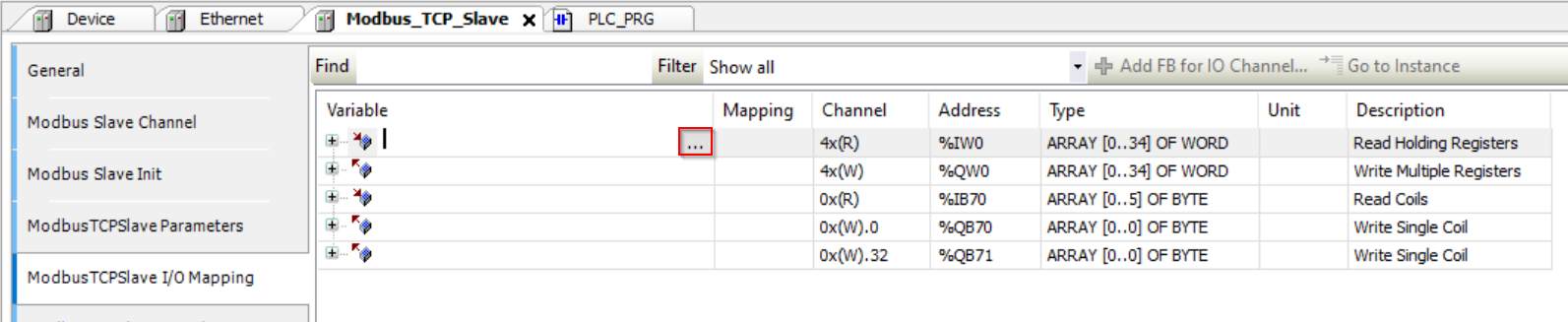
To map a variable to a Modbus address select the “ModbusTCPSlave I/O Mapping” tab:
-
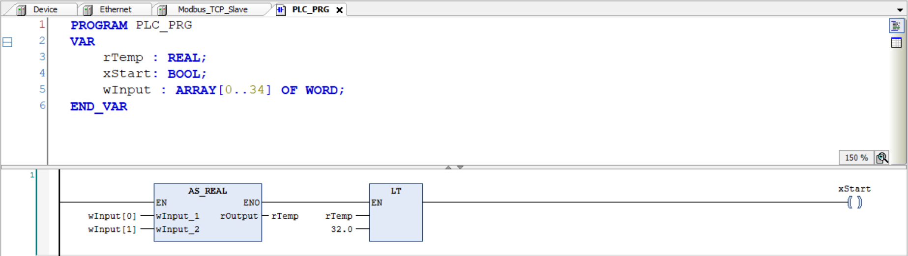
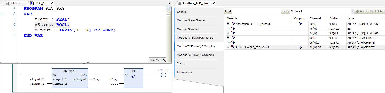
Declare a variable within a POU, GVL, or PVL:
Note: Here is an example in which we declare a variable within a POU and map it to I/O within a Modbus TCP slave: 4:32.
-
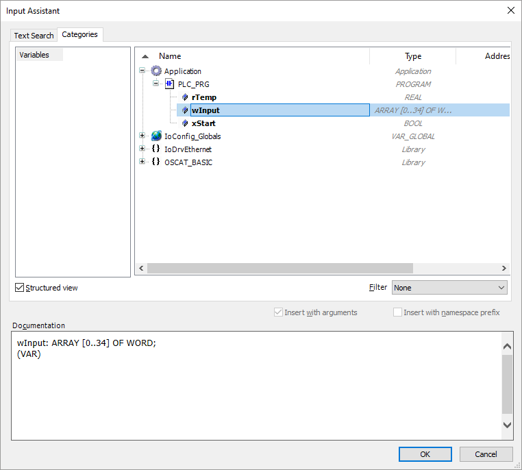
Once a variable has been declared, select the “ModbusTCPSlave I/O Mapping” tab within the Modbus TCP Slave device and double-click next to the desired I/O point in the “Variable” column. When prompted, click on the ellipses:
-
Ensure that the desired project variable is selected and click “OK” to map this variable to the I/O point:
Note: If the variable mapped to an IO point is not used within the ladder, the data within the IO point will not be polled by the PLC.
Tips:
-
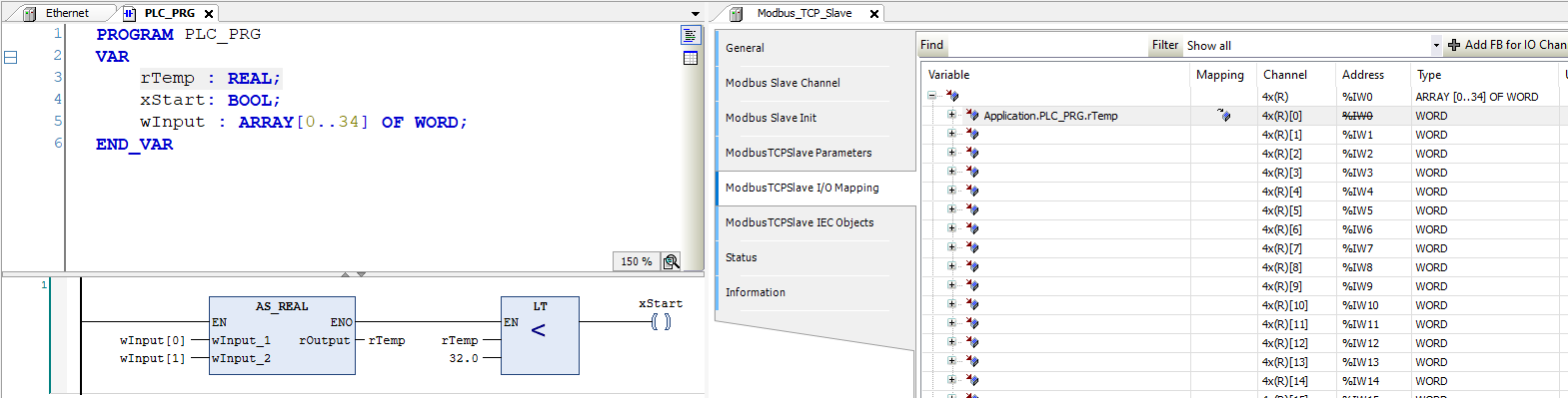
Note: Each variable mapped to a channel should match the array type. Therefore, it is not possible to map a variable of type REAL or DINT to a channel with an array type of WORD and the mapping defined below is invalid.
-
Codesys must write the correct number of registers and at the correct offset such that accidentally or intentionally writing a single WORD within a DWORD does not occur.
Note: The mapping below is invalid since Codesys is writing to only 16-bits within a REAL value. Therefore, the Modbus server cannot process this request.
-
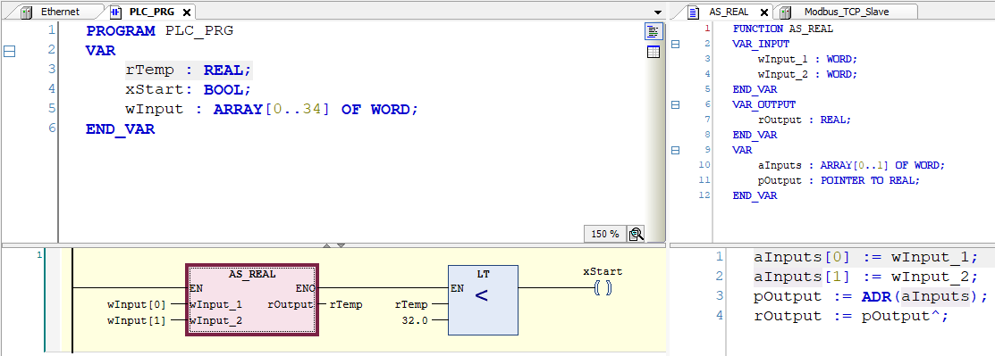
To convert two array elements of type WORD to REAL the following conversion function may be used:
-
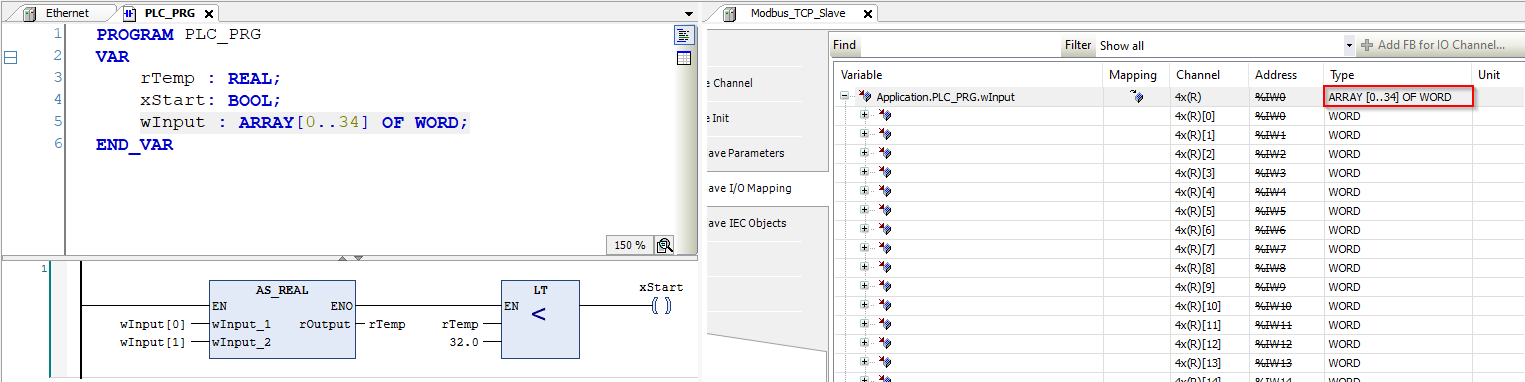
A variable with type “ARRAY[..] OF WORD” can be “mapped” to a channel with an equivalent array size and type:
-
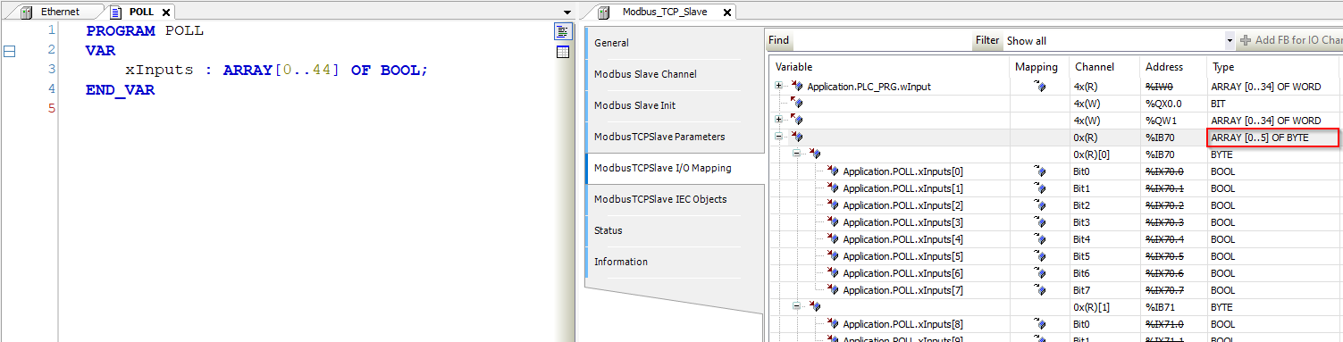
Each element in a variable with type “ARRAY[..] OF BOOL” should be mapped to each channel bit separately since the type does not match:
Note: If channel mapping is defined incorrectly, certain array elements may be listed as “Invalid”.
-
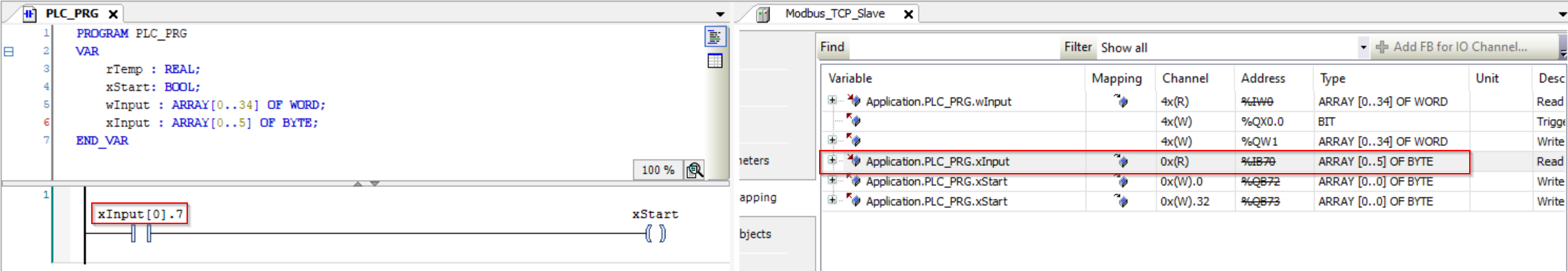
If an “ARRAY[..] OF BYTE” is mapped to a channel with access type “Read Coils”, it is possible to specify bit level access with elements in the byte array:
Note: In this example bit 7 of byte 0 is used within a contact in the POU.
-
A single boolean or word variable may be mapped to a channel that contains only one element:
Project download:
-
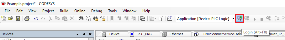
When the project is finished, please click the “Login” button to download this project to the HMI:
-
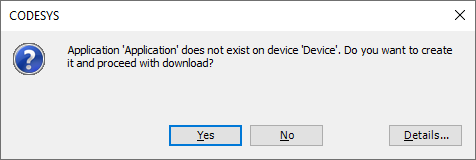
If prompted to “proceed with download” click “Yes”:
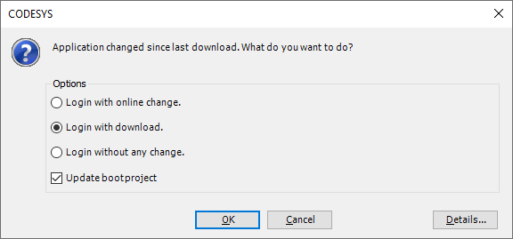
Note: Subsequent changes may display the following menu. If prompted, ensure that “Login with download” and “Update bootproject” are enabled.
-
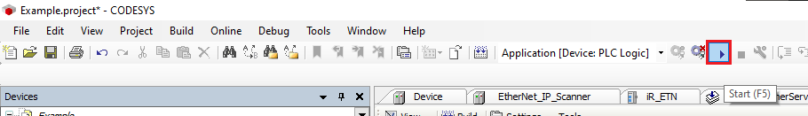
Click the “Start” button to place the Codesys application in “RUN” mode:
Keywords
Keywords:
Codesys to Rockwell, Codesys to CompactLogix, Codesys to Modbus RTU, Codesys to MicroLogix