- HMI Model: MT8071iP
- EasyBuilder Pro Version: latest
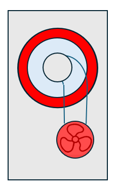
I am a new user - still becoming familiar with EasyBuilder. For my first HMI/PLC project I want to depict a particular item of equipment which has 5 states (fault, out-of-service, off, standby, running). I have created bitmap graphics for each of these states (built-up from standard shapes. Below is the “Fault” State version - attached as JPEG (I cannot attach a BMP). The other states have the same basic arrangement but with different coloring etc.
The particular image to be displayed is based on different binary variables in the PLC. I now need to add these to my HMI and set up switching between the different state-displays.
I am finding the shape/picture library aspect of the HMI somewhat difficult to learn. The manual does not cover customs graphics. The tutorial video https://www.youtube.com/watch?v=Ct0F8oD4xG4
covers multi-state objects fairly well - but I still need to figure out how to add my custom images, and how to link to specific PLC tags. (I have already loaded all the PLC tags into Easybuilder)
Q1: do I treat these images as “shapes” or “pictures”?
Q2: How do I incorporate them into my HMI?
As I understand, I have to:
- copy my bitmaps into the shape(?) project library
- add to the relevant HMI window
- link to the relevant PLC tags
Among the many Weintek tutorial videos I have watched previously, I recall there was one that included some instructions on how to setup custom shapes/pictures - but I cannot remember which one. Would you please remind me which tutorial covers creating custom shapes/pictures? Even better, provide a link? Perhaps there is an “instruction sheet” for this task?
Q3: While I have 5 states, so far only 4 of them have specific PLC binary variables. The “OFF” state is when none of the other 4 states apply. I could define a 5th PLC binary variable to represent “OFF”, but I wonder is it possible to set up (say) Object State 0 as a “default” - to apply if none of the other 4 states are active?
Thank you
Hi @BrianF_NZ ,
Thank you for your question.
Below are two posts. The first explains how to add a custom image to your project—please use it to add your custom images. The second shows how to use a multi-state button to display different images per state, so you can do something similar with your custom images.
Then, from your PLC, you can map each binary value to a state in your multi-state switch. You can also use a macro to change the switch’s state based on the binary value from the PLC.
Please let me know if you have any questions.
Hi Aaron, Thank you for your help so far.
I have successfully added my BMP graphics to the Project Picture Library as a 5-state picture. But I am having trouble assigning the different PLC variables that correspond to each of the 5-states.
Just checking … a “Multistate Object” is the same thing as a “Multistate Switch” - correct?
In case it was not clear previously, I have 4 different PLC-Binary tags - each intended to trigger a different state of the picture. My tags are normally mutually exclusive (not for testing)
When setting up a MS Switch I assign a single PLC tag and attach the picture. However, I gather the MS Switch is expecting a “word” input to reflect the different states, rather than independent binary tags I have.
Maybe I need a different approach?
As an experiment I set up a bitlamp driven from one PLC binary input switch, and inserted one of my images for state1 with state0 being Transparent. When I toggle the (physical) switch on PLC the image flips from transparent to correct. By overlapping several images I can get my desired result. It however difficult to select each of the superimposed objects to edit their attributes. Also, the image associated with the most recently activated bit superimposes above all the others
While this works adequately - I wonder if there is a better way to achieve the result??
Hi @BrianF_NZ ,
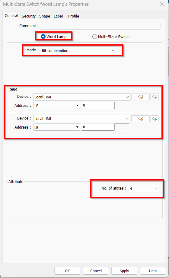
Could you change your multi state switch object into a Word Lamp, within the general tab of the object. This will allow you to select “Bit combination” as your mode so that you can read in your bits. Also please set the correct number of states you need so that the bit value matches up with the state the object is in.
Thank you!
Thank you Aaron
Converting to a Word Lamp has been successful - with a little adaptation.
Word lamp responds to the combined binary value the input tags, so
- pic0 displays with all input tags off
- pic1 displays with 1st input tag on
- pic2 displays with 2nd input tag on
- pic3 displays with 1st & 2nd input tags on
- pic4 displays with 3rd input tag on
- etc
Since I have 4 independent binary variables driving the Word Lamp, combinations are logically invalid. I resolved this by a combination of:
- increasing the number of states until 4 inputs become available - ie 9 states
- duplicating pictures for variable combinations.
After some experimentation I was able to achieve a suitable result using my 4 binary tags to show 5 states (actually 7 states but 2 pictures are duplicated)
Now I can move on to my next problem…
1 Like
Hi @BrianF_NZ ,
Glad to hear your project is working! Also thank you for coming back and doing a write up of your work!
Please let us know if any other questions come up!